Posts

Showing posts with the label PIC

Introduction to the PIC32 - The Basics, Getting Started, IO ports and the First Program

View on Scribd View in Google Docs Download PDF (4shared)

PIC32 DMA+SPI+DAC : Analog output synthesis with zero CPU overhead

Image
I have previously shown how to use the PIC32 SPI module to use the 12-bit DAC MCP4822: http://electel.blogspot.com/2016/10/pic32-spi-using-mcp4822-12-bit-serial.html . While that does allow you to generate analog outputs as desired, it requires you to use CPU cycles to process the timer interrupt and accordingly drive the SPI module. Since the PIC32 contains DMA channels, the process can be completely offloaded from the CPU. For an idea of the PIC32 DMA module, refer to my previously written article: http://electel.blogspot.com/2016/05/simple-pic32-dma-example.html Fig. 1 - The generated sine wave at fpwm = 400kHz and 32 elements in the sine table So, the simple way of offloading the SPI update to the DMA module would be to let the DMA channel transfer data to the SPI buffer. The SPI module is configured for 16-bit data transfer (since the MCP4822 write command requires 2 bytes). This means that the cell size for the DMA channel has been set to 2 (2 bytes to transfer once triggered). T...

PIC32 Tic-Tac-Toe: Demonstration of using touch-screen, TFT and the Protothreads threading library

Image
I had previously used the Adafruit TFT display using my library (ported from the Adafruit Arduino library). I decided to optimize the library to improve drawing speed. The same display I use comes with a 4-wire resistive touch-screen as well. I decided to write a simple library for the touch-screen and give Protothreads a try. To incorporate all this, I thought it would be cool if I used these to make a simple game. Tic-tac-toe came to mind as a fun little demo. I'm sure everyone's familiar with the game so I won't explain the rules there. The touch-screen is simply two resistive sheets placed on top of each other on top of the TFT screen. When it is pressed down at a given place, the two sheets make contact and a voltage divider is formed. Using the IO's and the ADC, this voltage is read in the X and Y directions to register a touch. Here is a very good pictorial depiction of the resistive touch screen (taken from the Atmel AVR341 document ): So in order to...

AC Power Control with Thyristor: Phase Angle Control using triac with PIC16F877A

Image
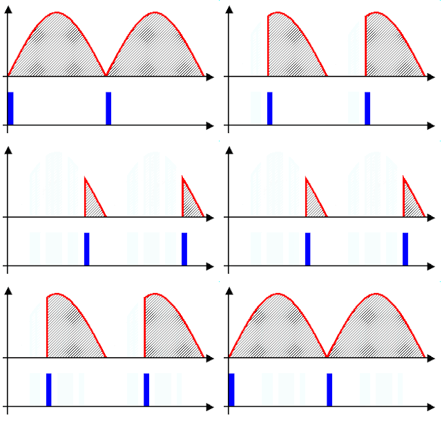
Principle of Phase Angle Control Top - Output Voltage Bottom - Gate Drive Signal Image source: Wikipedia (http://en.wikipedia.org/wiki/File:Regulated_rectifier.gif) The photo above clearly illustrates phase angle control: output voltage controlled by the gate drive signal applied to a thyristor. What is phase angle control? That is what I'm going to talk about in this article. Phase angle control is a method of PWM applied to AC input voltages, usually the mains supply. Of course, the AC supply could be from a transformer or any other AC source, but the mains supply is the most common input – this gives the phase angle control method its greatest usefulness. It has of course become quite obvious from the title (and I’m sure most of you reading will already know this) that the purpose of phase angle control is to control or limit power to the load. The power device used in phase angle controllers is a thyristor – mostly triacs or SCRs. (There are methods of phase controlling employi...

Creating my own TV Tuner IR remote with a PIC16F684

Image
While I was home this winter, I saw that the remote for our TV tuner was damaged physically, causing the buttons to not function responsively. Some of them just didn't work. I saw this as an opportunity for a fun couple days' project to build a new remote controller for the tuner. The TV tuner was manufactured by a brand name RealView and, as expected, I couldn't find much detail about it. Thus, I had to reverse engineer the remote. From my previous experience in working with IR remotes, I had a hunch that the IR was most likely modulated at ~38kHz or ~56kHz. For those of you who don't know how this works, I highly recommend going through this website: http://www.sbprojects.com/knowledge/ir/ Thus, I connected a 38kHz IR receiver I had at home (TSOP1738) to an oscilloscope in order to figure out what IR protocol is used by the remote. Upon pressing the 4 key on the remote, I saw the following waveform: Fig. 1: Oscilloscope waveform capture of the received IR signal Note...

Turn off Led using PIC16f877a with Assembler Code

Image
Start making a simple program in which we in assembly code using PIC 16F877A to turn on and off an LED by pressing a button as shown in the diagram. We will use two ports of the PIC 16F877A, port B and port D, declare the B port as input and the D port will be configured as an output. In the graph we can see that the pin RB0 is set button and a resistor in a pull-up configuration, when you are not pressing the button it gets a high (5V) to the RB0 input and when pressed he gets a level low (0V). In the output RD0 to turn on the led its output should be at a low level so when developing the program in assembler we test the pin B0 and if a high level put a high value on the output RD0 that will keep off LED, otherwise put a low value on the output RD0 which will cause the LED lights.