Posts

Showing posts with the label push-pull

Ferrite Transformer Turns Calculation for High-Frequency/SMPS Inverter
Image
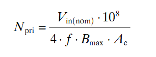
On different forums, I often find people asking for help in calculating the required turns for a ferrite transformer they are going to use in high-frequency/SMPS inverters. In a high-frequency/SMPS inverter, the ferrite transformer is used in the step-up/boost stage where the low voltage DC from the battery is stepped up to high voltage DC. In this situation, there are really only two choices when selecting topology – push-pull and full-bridge. For transformer design, the difference between a push-pull and a full-bridge transformer for same voltage and power will be that the push-pull transformer will require a center tap, meaning it will require twice the number of primary turns as the full-bridge transformer. Calculation of required turns is actually quite simple and I’ll explain this here. For explanation, I’ll use an example and go through the calculation process. Let’s say the ferrite transformer will be used in a 250W inverter. The selected topology is push-pull. The power source...

Using the SG3525 PWM Controller - Explanation and Example: Circuit Diagram / Schematic of Push-Pull Converter

Image
PWM is used in all sorts of power control and converter circuits. Some common examples include motor control, DC-DC converters, DC-AC inverters and lamp dimmers. There are numerous PWM controllers available that make the use and application of PWM quite easy. One of the most popular of such controllers is the versatile and ubiquitous SG3525 produced by multiple manufacturers – ST Microelectronics, Fairchild Semiconductors, On Semiconductors, to name a few. SG3525 is used extensively in DC-DC converters, DC-AC inverters, home UPS systems, solar inverters, power supplies, battery chargers and numerous other applications. With proper understanding, you can soon start using SG3525 yourself in such applications or any other application really that demands PWM control. Before going on to the description and application, let’s first take a look at the block diagram and the pin layout. Pins 1 (Inverting Input) and 2 (Non Inverting Input) are the inputs to the on-board error amplifier. If you a...