[Tutorial] Making a Cheap BLUETOOTH connection device
Ready Bluetooth solutions are often quite expensive. The cheapest Bluetooth modules that are currently commercially available, there are from the Chinese manufacturer Rayson . The modules BTM-112 (Class 2) and BTM-222 (Class 1) each cost around 15 €.
Since the modules are designed for 3.3V supply voltage is required for connection to a 5V system in addition to a 3.3V voltage regulator for 2 level converter (Level Shifter) for the UART signals. In addition, you do not want to give up a status display with LED safely. The price of a module is still all in all about 20 €.

The circuit
The circuit of the Bluetooth module is designed to operate on a 5V system. As a voltage regulator, a controllable LM317L is used.Similarly, a 3.3V voltage regulator such as the LF33CV could be used.


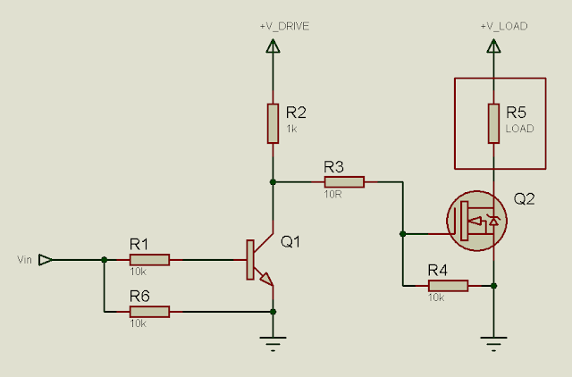
Level converter
A level converter (English Level Shifter) is used to adjust signal levels of different voltage levels. A typical example of a level converter is for example a RS232 converter. This converts the 12V level RS232 interface 5V TTL level.
The level converter for our Bluetooth module from each of 2 NPN transistors formed and a few resistors. Theoretically you could 3.3V to 5V by Level omit shifter because the 3.3V level are normally recognized as a HIGH level. Similarly, the 5V 3.3V level shifter could be argued by a voltage divider consisting of only 2 resistors to replace. But I'd rather go here on the safe side.
External antenna
Both modules have no antenna. But what more is not bad, a piece of wire do it just as well. It may thus achieves an even higher range than a ceramic antenna. In particular, a so-called lambda / 4 antenna is required. The length of a lambda / 4 antenna corresponds to a quarter of the transmit frequency in Bluetooth (2.4GHz) gives the length of 31mm.
Adapter board
First, the BTM-222 module is brought to the standard grid of 2.54mm. For this purpose, the module is stuck in the middle with hot glue on a piece of breadboard size 40 x 25mm. Double-sided point grid is ideal for this purpose. The contacts are necessary for the operation performed on two 9-pin headers. Of these, only 7 contacts are total needed, however. The main problem here turned out to find appropriate wires to be wired to the module. The thinnest, at my disposal silver wire with 0.4 mm diameter, was there still fat. After some trial and error was the appropriate "wire" found. The single copper from a piece of flexible electric cables were easily soldered to the Winz contacts of the module. Only for the ground connection standard wire with 0.6 mm was used. The blocking capacitors were also soldered with this adapter board.Thus, the module could already be fully integrated in a 3.3 system.But for 5V system is still a few little things.

Commissioning
Bluetooth profiles
Data exchange via Bluetooth using so-called profiles. When connecting the devices exchange their profile information and agree on the profile used here
Support both BTM Module (BTM-112 and BTM-222), the SPP profile (S erial P ort P rotocol). Thus, the activation of both the PC side as well as from the microcontroller side is particularly simple.From the PC side (Bluetooth) the device behaves like a COM interface. Microcontroller side (Serial) only the UART RXD TXD and needed. The whole is referred to as "cable replacement solution." That is, the application software and the connected microcontroller hardware does not notice everything behaves as a normal serial cable connection.
Sample structure on breadboard
By Headers can simply plug the Bluetooth module on a breadboard order to build the rest of the circuit for the 5V logic and test. These include the 3.3V power supply status LEDs and a couple of the two level shifter.

First attempts
The first experiments with the sample structure consisted only of the module and a few status LEDs on the ports PIO5..7 with a 3.3V DC power supply. This can be ever test the power consumption. After the voltage 50mA flows duch the circuit. The LED on PIO5 flashing 2x briefly along with the LED on PIO7. After that, only the LED was blinking 2 times per second PIO7. The ever looked not bad. Also under the Bluetooth environment on the PC was to find an unknown device. A connection but let not build up.This is only the beginning namely directly via the serial interface.
1. serial connection
To configure the Bluetooth module, a serial connection is unique to the PC via an RS232 adapter or a USB-UART converter needed.The RS232 Wnadler sets the UART TTL level (0V..5V) in RS232 to level (+ 12V ..- 12V). A USB-UART converter is necessary for modern PCs that do not have a RS232 interface. Caution must be UART TTL level converter with USB UART. The standard USB-RS232 converters operate on the serial interface with RS232 level again, then why in addition to the Bluetooth module in turn a RS232-TTL converter would be necessary.
The pictured below homemade RS232 UART converter consists of a MAX202 chip and 4 capacitors.

In the terminal program following the serial port settings are required:
"19200 baud, 8 data bits, no parity, 1 stop bit, no handshake or hardware"
After applying the supply voltage, the module responds to AT commands that you enter the terminal program. On 'AT' the module responds with 'OK'. The complete set of instructions can be found in the datasheet . Some commands funktioneren only in the master mode. Since our module operates as a slave, it returns an error message 'ERROR' when entering appropriate commands.On the command 'ATB?' the module responds with its Bluetooth address. ATI? ' provides the firmware version ('v4.19' with my module).
Correction from 31.12.2010:
Finally, the command 'ATH1' and not 'ATH0' sufficient as previously described for the module allows up a connection via Bluetooth. Etc. A special pairing with input from pin code is not necessary.
Correction from 02.07.2008: The above command 'ATH1' is not necessary that is already the default setting. If there are problems, it is sufficient to perform a factory reset with 'ATZ0'.
1. Bluetooth connection
Now it will produce a first-time connection via Bluetooth. When applying the voltage to the module, I notice that now varies widely, the current consumption (between 20..70mA in second intervals).But no need to worry, everything is normal. Who is now around double-clicking under the Bluetooth on your PC to the 'Serial Adaptor Dev B' gets a connection, and you get the COM number under which the module is under Bluettoth reached (COM3 in my case). Drop these COM number in the terminal program, the other parameters such as baud rate are the same as described above.When successfully connected, the power consumption is due to 20mA and the green status LED continuous light now. If you pressed a button in the terminal program lights to the red LED Traffic. Perfect, so that's fun.
For future connections, it is sufficient to start the terminal program.The connection is then within 2-3 seconds.
Carrier Board
Now we have to make the circuit of the sample structure on eie breadboard. Thus, the entire module is not too big, I opt for a sandwich construction. Most data components then sit under the adapter board. A lot of space is not, but with upending the most resistors it works without problems to accommodate everything.However, one must make sure that the parts do not protrude too high, otherwise there could be short-circuiting the adapter board.The pin assignment of the 6-pin connector corresponds to the assignment of my BlueSMiRF or RS232 module. So I can replace the modules with one another as.
The carrier board component side:

The carrier board solder side:

Carrier board layout plan component page:

Carrier board layout plan solder side:

The final module
Managed, so does the finished module. Before plugging you should definitely by measuring the carrier board and test it first time alone. That is measure Stromaufahme, check voltages. The 3.3V supply voltage must be adjusted only via the potentiometer.Only then should you insert the module. As with the test setup should only create tension when both LEDs flash briefly, then cyclically only the green LED.

BOM
1 LM317LZ adjustable voltage regulator IC1
1 Bluetooth module BTM-222, IC2
NPN transistor BC547 4 o. ä., T1..T4
1 red LED, low current 2mA, D1
1 LED green low current 2mA, D2
1N4002 diode 1, D3
4 Film capacitors 100nF, C1..C4
8 resistors 1k, R1..R8
1 resistor 220, R9
1 trimmer 5k, R10
2 power strips just 2.54mm 9-pin
plug connector angled 1, 6-pin 2.54mm
2 Sockets just 9- 2.54mm pin
1 piece of double-sided prototype dot grid, 25x40mm
1 piece of prototype unilaterally dot grid, 30x53mm
silver wire, 0.4mm
insulated hookup wire, rigid, red, yellow, black 0.4mm
copper wire made of flexible electric cables
Thats all folks!
Via robotfreak.de
Note: If you have any problem while making this BLUETOOTH connection device, feel free to comment below :)

I remember a time when my mother gave me a Bluetooth device which I hate but in the end it was useful to me.
ReplyDelete