Electronic digital lock circuit
* Map principles:
Activity:
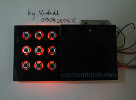
If you want your house to be modern, mount it on lock! I used it two years ago (perhaps twenty years still runs fine) There are many who intend to "crack" but without success. This is the principle of it vessels. When you have made in addition to the protection circuit howling whistle when pressing the wrong code, or does not allow detection code (to be introduced later) principle: CD IC 4017 is the output row count is 10, corresponding to the clock, then turn the output will be high. we take advantage of this feature to give a high output back to input clock by hand coding phim.Khi new power circuit, IC is reset, output Q0 is high, this time if you press the number 2 the higher will be put into making the IC pin count clock to the output of Q2 is a high level, if you continue to press the number 0, then jump onto the high Q3 ... press the correct keys in turn will lead to Q6 high level to enable the circuit to unlock. If you press the wrong, what happens? If you press the wrong number, the C828 is polarized upon through D1 into the reset pin. IC will return to its original state. Depending on the arrangement of the diodes that you have the code different numbers. Code of this circuit is 280 858 (This is me mother's birthday!). I wish you success! # Components: IC CD4017


Comments
Post a Comment