Decoding IC 74LS47 7 segment LED
Click to enlarge

Video demo

- One of the most popular electronic IC number. There are many different symbols depending on the firm and ability to meet such as 74HC47, 74HCT47, 74LS47,.
Application:
This is a sign dedicated decoder IC for LED 7-segment common anode. Application when it needs to display the number on the LED 7-in digital circuit without using the processor or want to save the foot.''

The mode of operation:
- Map of principle: As the diagram above, in which A, B, C, D (Connect with the processor, pulse the counter ,...), BI / RBO, RBI, LT (7447 foot control, depending on different needs will be connected), Chan QA, QB, QC, QD, QE, QF, QG, respectively connected to pin a, b, c, d, e, f, g of common anode 7-segment LED.
- Describe how the following activities:
PORT A, B, C, D: input of 7447, receiving the binary value (BCD) from 0 to 15, corresponding to each value received will decode the output Q, respectively.
QA-QG PORT: Connect directly to LED 7 = a bar with QA, QB = b, c = QC, QD = d, e = QE, QF = f, QG = g, the value displayed on the LED 7-dependent the input value Porta, B, C, D in the following table;
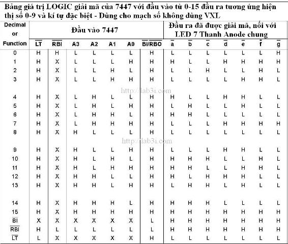
BI / RBO, RBI, LT: 7447 Chan's control, to understand you need to read and understand the following logic table (IC 7447 To enable the connection works just BI / RBO = LT = 1):
The downside, cost IC pins, use 7-segment LED scanning method is more effective to use transistor, IC pins support costs


làm bằng đại học
ReplyDeletelàm bằng đại học uy tín
làm bằng đại học giá rẻ
làm bằng đại học tại tphcm
làm bằng đại học tại hà nội
làm bằng đại học không cần đặt cọc