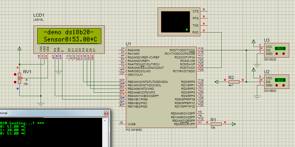
Make a Digital Thermometer Circuit with IC DS18B20 + PIC 18F4550 (Source code included)
Hello guys. Today I will guide you how to make a Digital Thermometer Circuit using IC DS18B20 and PIC 18F4550. I also provide you the source code of this project. Thank you for reading my blog :)
Please go through the characteristics of IC DS18B20 and PIC 18F4550 that can be used to make a Digital Thermometer Circuit first and then run the code below.
For PIC18F4550:
- Flash: 32K bytes
- Single-Word Instructions: 16384
- SRAM: 2048 bytes
- EEPROM: 256 bytes
- I/O: 35
- 10-Bit A/D (ch): 13 Y Y 1
- CCP/ECCP (PWM): 1/1
- SPP: Yes
- SPI: Yes
- Master I 2C™: Yes
- EAUSART: 1
- Comparators: 2
- Timers 8/16-Bit: 1/3
Special Microcontroller Features: • C Compiler Optimized Architecture with optional Extended Instruction Set • 100,000 Erase/Write Cycle Enhanced Flash Program Memory typical • 1,000,000 Erase/Write Cycle Data EEPROM Memory typical • Flash/Data EEPROM Retention: > 40 years • Self-Programmable under Software Control • Priority Levels for Interrupts • 8 x 8 Single-Cycle Hardware Multiplier • Extended Watchdog Timer (WDT): - Programmable period from 41 ms to 131s • Programmable Code Protection • Single-Supply 5V In-Circuit Serial Programming™ (ICSP™) via two pins • In-Circuit Debug (ICD) via two pins • Optional dedicated ICD/ICSP port (44-pin devices only) • Wide Operating Voltage Range (2.0V to 5.5V)
Download Datasheet for PIC18F4550 here
For IC DS18B20:
The DS18B20 Digital Thermometer provides 9 to 12-bit (configurable) temperature readings which
indicate the temperature of the device.
FEATURES Unique 1-Wire interface requires only one port pin for communication Multidrop capability simplifies distributed temperature sensing applications Requires no external components Can be powered from data line. Power supply range is 3.0V to 5.5V Zero standby power required Measures temperatures from -55°C to +125°C. Fahrenheit equivalent is -67°F to +257°F ±0.5°C accuracy from -10°C to +85°C Thermometer resolution is programmable from 9 to 12 bits Converts 12-bit temperature to digital word in 750 ms (max.) User-definable, nonvolatile temperature alarm settings Alarm search command identifies and addresses devices whose temperature is outside of programmed limits (temperature alarm condition) Applications include thermostatic controls, industrial systems, consumer products, thermometers, or any thermally sensitive system
Tags: thermostat, thermocouple, barometer, thermostats, digital thermostat, braun thermoscan, pyrometer
SOURCE CODE:
File: main.c
 |
| Digital Thermometer Circuit |
For PIC18F4550:
- Flash: 32K bytes
- Single-Word Instructions: 16384
- SRAM: 2048 bytes
- EEPROM: 256 bytes
- I/O: 35
- 10-Bit A/D (ch): 13 Y Y 1
- CCP/ECCP (PWM): 1/1
- SPP: Yes
- SPI: Yes
- Master I 2C™: Yes
- EAUSART: 1
- Comparators: 2
- Timers 8/16-Bit: 1/3
Special Microcontroller Features: • C Compiler Optimized Architecture with optional Extended Instruction Set • 100,000 Erase/Write Cycle Enhanced Flash Program Memory typical • 1,000,000 Erase/Write Cycle Data EEPROM Memory typical • Flash/Data EEPROM Retention: > 40 years • Self-Programmable under Software Control • Priority Levels for Interrupts • 8 x 8 Single-Cycle Hardware Multiplier • Extended Watchdog Timer (WDT): - Programmable period from 41 ms to 131s • Programmable Code Protection • Single-Supply 5V In-Circuit Serial Programming™ (ICSP™) via two pins • In-Circuit Debug (ICD) via two pins • Optional dedicated ICD/ICSP port (44-pin devices only) • Wide Operating Voltage Range (2.0V to 5.5V)
Download Datasheet for PIC18F4550 here
For IC DS18B20:
 |
| IC DS18B20 Pin Assignment DS18B20Z 8-Pin SOIC (150 mil) |
FEATURES Unique 1-Wire interface requires only one port pin for communication Multidrop capability simplifies distributed temperature sensing applications Requires no external components Can be powered from data line. Power supply range is 3.0V to 5.5V Zero standby power required Measures temperatures from -55°C to +125°C. Fahrenheit equivalent is -67°F to +257°F ±0.5°C accuracy from -10°C to +85°C Thermometer resolution is programmable from 9 to 12 bits Converts 12-bit temperature to digital word in 750 ms (max.) User-definable, nonvolatile temperature alarm settings Alarm search command identifies and addresses devices whose temperature is outside of programmed limits (temperature alarm condition) Applications include thermostatic controls, industrial systems, consumer products, thermometers, or any thermally sensitive system
Tags: thermostat, thermocouple, barometer, thermostats, digital thermostat, braun thermoscan, pyrometer
SOURCE CODE:
File: main.c
#include "main.h"
#define DS1820_DATAPIN PIN_C0
#include "types.h"
#include "ds1820.h"
#include "lcd4bit.h"
int16 temperature_raw;
float temperature_float;
char temperature[8];
int8 sensor_count;
//unsigned char str[20];
void main(void)
{
setup_adc_ports(NO_ANALOGS|VSS_VDD);
setup_adc(ADC_CLOCK_DIV_2);
setup_psp(PSP_DISABLED);
setup_spi(SPI_SS_DISABLED);
setup_wdt(WDT_OFF);
setup_timer_0(RTCC_INTERNAL);
setup_timer_1(T1_INTERNAL|T1_DIV_BY_8);
setup_timer_2(T2_DISABLED,0,1);
setup_ccp1(CCP_OFF);
setup_comparator(NC_NC_NC_NC);
setup_vref(FALSE);
//TODO: User Code
lcd_init();
lcd_putc(" -Digital Thermometer-");
lcd_gotoxy(1,2);
lcd_putc("http://electel.blogspot.com/");
delay_ms(2000);
fprintf(UART, "Digital Thermometer Source code using IC DS18B20 + PIC 18F4550!");
fprintf(UART, "\n\r*** DS1820 Loading...! ***\n\r");
delay_ms(500);
sensor_count = 0;
while (TRUE)
{
if ( DS1820_FindFirstDevice() )
{
do
{
temperature_raw = DS1820_GetTempRaw();
DS1820_GetTempString(temperature_raw, temperature);
temperature_float = DS1820_GetTempFloat();
fprintf(UART, "Sensor %d: %f *C \n\r", sensor_count, temperature_float);
lcd_gotoxy(1,2);
//printf(lcd_putc"Temperature: %3.1f*C",temperature_float);
printf(lcd_putc"_Sensor%d:%f*C\n\r", sensor_count, temperature_float);
sensor_count ++;
}
while ( DS1820_FindNextDevice() );
sensor_count = 0;
}
delay_ms(1000);
}
}
File main.h
#include <18F4550.h>
#device adc=8
#FUSES NOWDT //No Watch Dog Timer
#FUSES WDT128 //Watch Dog Timer uses 1:128 Postscale
#FUSES HSPLL //High Speed Crystal/Resonator with PLL enabled
#FUSES NOPROTECT //Code not protected from reading
#FUSES NOBROWNOUT //No brownout reset
#FUSES BORV20 //Brownout reset at 2.0V
#FUSES NOPUT //No Power Up Timer
#FUSES NOCPD //No EE protection
#FUSES STVREN //Stack full/underflow will cause reset
#FUSES NODEBUG //No Debug mode for ICD
#FUSES NOLVP //No low voltage prgming, B3(PIC16) or B5(PIC18) used for I/O
#FUSES NOWRT //Program memory not write protected
#FUSES NOWRTD //Data EEPROM not write protected
#FUSES IESO //Internal External Switch Over mode enabled
#FUSES FCMEN //Fail-safe clock monitor enabled
#FUSES PBADEN //PORTB pins are configured as analog input channels on RESET
#FUSES NOWRTC //configuration not registers write protected
#FUSES NOWRTB //Boot block not write protected
#FUSES NOEBTR //Memory not protected from table reads
#FUSES NOEBTRB //Boot block not protected from table reads
#FUSES NOCPB //No Boot Block code protection
#FUSES MCLR //Master Clear pin enabled
#FUSES LPT1OSC //Timer1 configured for low-power operation
#FUSES NOXINST //Extended set extension and Indexed Addressing mode disabled (Legacy mode)
#FUSES PLL5 //Divide By 5(20MHz oscillator input)
#FUSES CPUDIV1 //No System Clock Postscaler
#FUSES USBDIV //USB clock source comes from PLL divide by 2
#FUSES VREGEN //USB voltage regulator enabled
#FUSES ICPRT //ICPRT enabled
#use delay(clock=48000000)
#use rs232(baud=9600,parity=N,xmit=PIN_C6,rcv=PIN_C7,bits=8,stream=UART)
If you get any problem running this source code, feel free to comment below. Thank you!


doesnt work
ReplyDeletedoesnt work
ReplyDeleteIt is a device which helps to measure the temperature gradient or temperature of human beings by calculating some body temperature.Digital Thermometer
ReplyDeleteThe Forehead and Surface Infrared Thermometer from SantaMedical is specially designed to obtain the most accurate temperature readings of tear ducts or the forehead. The temperature on the forehead reads from 1” to 4” away. The temperature is displayed on the LCD screen and it has a backlight for enabling the night time usage and it can even display results in total darkness. The thermometer features the audio alarm for alerting whenever the person is suffering from the high temperature.
ReplyDeleteWow, this is an awesome and creative blog. Thanks for sharing this much useful post with us...
ReplyDeleteWholesale Digital Thermometers
This article is very good. I like it.Interesting post. Thanks for posting this.Please share more information
ReplyDeletebest digital thermometer
Thank for sharing this impressive blog. Buy Accusure digital thermometer.
ReplyDelete