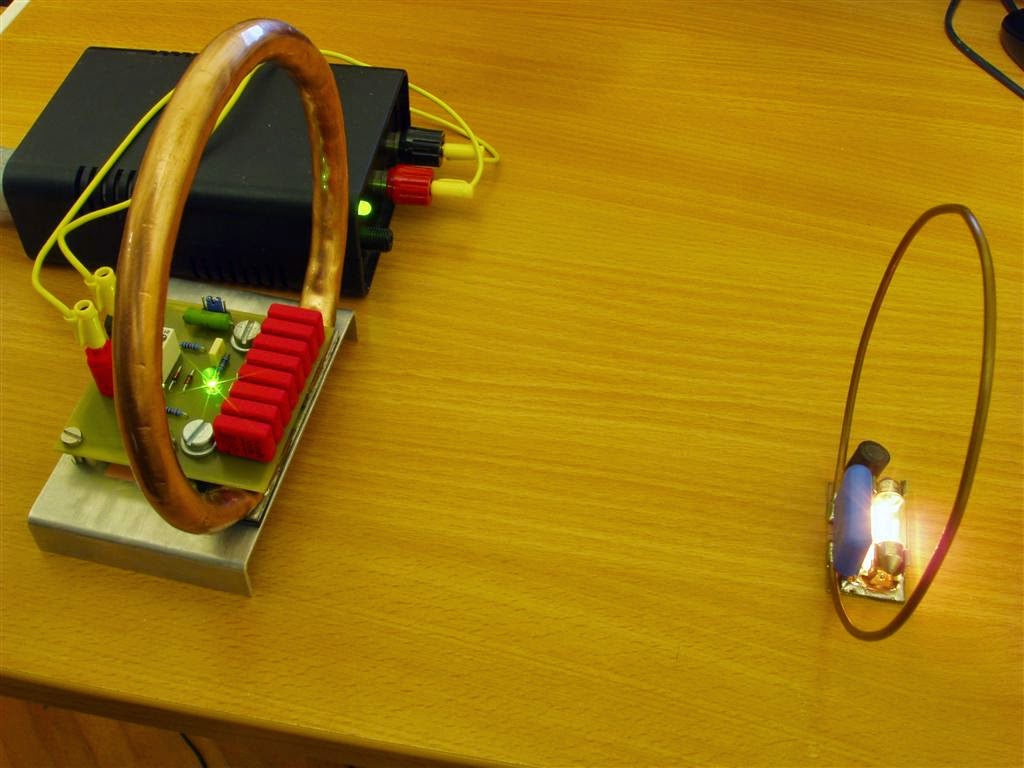
Building a Simple Wireless Energy Transfer Circuit step-by-step
In this article, I will show you how to build a simple Wireless Energy Transfer Circuit.
It's really simple circuit made of 5 parts, even a beginner shouldn't have any problems with building this.
I also improved it since my last video, made better secondary coils that work on larger/longer distances.
Things you will need:
1. Transistor BD139
Or you can use these alternatives: BD135, BD137, 2N4921, 2N4922, 2N4923, BDW55, BDW57, BDW59.
(You need only one, not all of them)
2. Foil capacitor 1nF 100V
Voltage should be more than 16V, you should use this one because of its size (it will fit on PCB as we need it)
Note that: 1000 means 1000pF = 1nF
tags: Wireless Energy Transfer Circuit
3. Foil capacitor 4.7nF - 100V
Note: 4700 = 4700pF = 4.7nF
4. Foil capacitor 100nF - 63V
Note: 0.1 means 0.1uF here; 100nF
5. Resistor 5k6 Ohm, 0.5W
6. And a 5x6 holes large piece of universal PCB.
Note: you need a PCB that has each hole separated.
OK Let's start!!!
Place 1nF capacitor into corner of PCB.
Orientation is not important, foil and ceramic caps don't have polarity.

Solder cap on PCB
Note: If you don't know how, please don't ask me and use the internet ;))

Place 4.7nF cap on PCB, like this

...and solder it

Place 5k6 resistor on PCB

Solder parts like on this picture. You can use resistor legs as wires to solder parts together.

Add transistor

Bend its legs like on this picture

Solder transistor with other parts

Add 100nF capacitor

Solder last transistor's leg to cap

Circuit is done! Now we need a primary coil.

Find something with 5cm diameter

Wind a coil with 5 turns

Wire should be made of copper, but you can use any material (iron, aluminium, etc...)
Wire must be insulted or enamel-led!
Use wire thicker than 0.3mm (28 AWG), so your coil will keep circular shape.
Solder another wire on end.

And wind another 5 turns, so you now have two coils connected together: 5 + 5t coil.

Use zip ties or tape to tie wires together, so coil keeps circular shape.

Coil end are reversed.
Place middle wire on PCB.

Solder wire to cap.

Strip wire, make it long.

Solder end wire to transistor's middle leg.

Make sure these two wires don't touch!

Prepare the last wire.

Solder wire to cap's leg.

Solder battery connector, wires, or whatever you want.
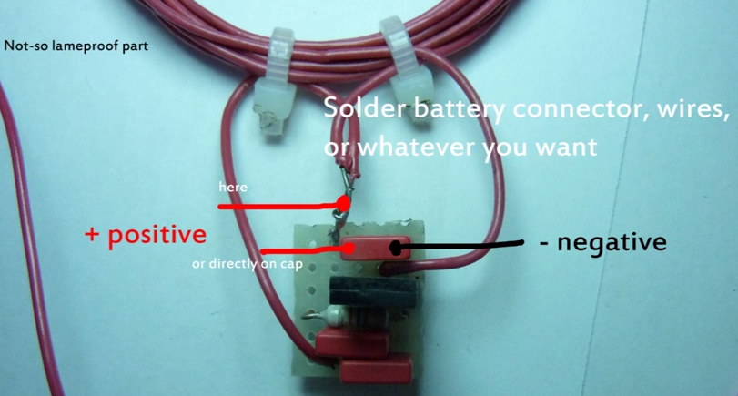
I personally use test hooks.

Supply voltage 4.5V-6V (3 or 4 1.5V cells)
Note: you can go up to 15V, but the oscillation frequency will change, and transistor will probably need little heat sink.
tags simple Wireless Energy Transfer Circuit
Secondary coils needs resonant capacitor, without it, the maximum transmission distance would be much smaller, here are capacities you need:
5 turns: 15nF
10 turns: 1nF
25 turns: 200 to 300 pf

Secondary coils are wound same as primary, except there is only one, without middle gap.
Wire must be insulated or enameled. You don't have to use capacitor, but it greatly increase transfer distance and power.
Connect cap in parallel with coil and diode.

Note 1: Red diodes work best, white worst. It is caused by voltage drop, red has lowest, white highest. This is not actually important, red LED will just work on larger distance than white.
Note 2: Capacitors on secondary coils can be foil, but also ceramic.
Author of this project: Dri0m
If you have any problem while doing this project, feel free to comment below.
It's really simple circuit made of 5 parts, even a beginner shouldn't have any problems with building this.
 |
| Wireless energy transfer circuit |
Things you will need:
1. Transistor BD139
 |
| Transistor BD139 |
(You need only one, not all of them)
2. Foil capacitor 1nF 100V
 |
| Foil capacitor 1nF 100V |
Note that: 1000 means 1000pF = 1nF
tags: Wireless Energy Transfer Circuit
3. Foil capacitor 4.7nF - 100V
Note: 4700 = 4700pF = 4.7nF
4. Foil capacitor 100nF - 63V
Note: 0.1 means 0.1uF here; 100nF
5. Resistor 5k6 Ohm, 0.5W
 |
| Resistor 5k6 Ohm, 0.5W |
 |
| 5x6 holes large piece of universal PCB |
OK Let's start!!!
Place 1nF capacitor into corner of PCB.
Orientation is not important, foil and ceramic caps don't have polarity.
Solder cap on PCB
Note: If you don't know how, please don't ask me and use the internet ;))
Place 4.7nF cap on PCB, like this
...and solder it
Place 5k6 resistor on PCB
Solder parts like on this picture. You can use resistor legs as wires to solder parts together.
Add transistor
Bend its legs like on this picture
Solder transistor with other parts
Add 100nF capacitor
Solder last transistor's leg to cap
Circuit is done! Now we need a primary coil.
Find something with 5cm diameter
Wind a coil with 5 turns
Wire should be made of copper, but you can use any material (iron, aluminium, etc...)
Wire must be insulted or enamel-led!
Use wire thicker than 0.3mm (28 AWG), so your coil will keep circular shape.
Solder another wire on end.
And wind another 5 turns, so you now have two coils connected together: 5 + 5t coil.
Use zip ties or tape to tie wires together, so coil keeps circular shape.
Coil end are reversed.
Place middle wire on PCB.
Solder wire to cap.
Strip wire, make it long.
Solder end wire to transistor's middle leg.
Make sure these two wires don't touch!
Prepare the last wire.
Solder wire to cap's leg.
Solder battery connector, wires, or whatever you want.
I personally use test hooks.
Supply voltage 4.5V-6V (3 or 4 1.5V cells)
Note: you can go up to 15V, but the oscillation frequency will change, and transistor will probably need little heat sink.
tags simple Wireless Energy Transfer Circuit
Secondary coils needs resonant capacitor, without it, the maximum transmission distance would be much smaller, here are capacities you need:
5 turns: 15nF
10 turns: 1nF
25 turns: 200 to 300 pf
Secondary coils are wound same as primary, except there is only one, without middle gap.
Wire must be insulated or enameled. You don't have to use capacitor, but it greatly increase transfer distance and power.
Connect cap in parallel with coil and diode.
Note 1: Red diodes work best, white worst. It is caused by voltage drop, red has lowest, white highest. This is not actually important, red LED will just work on larger distance than white.
Note 2: Capacitors on secondary coils can be foil, but also ceramic.
Author of this project: Dri0m
If you have any problem while doing this project, feel free to comment below.


Can I scale up the capacity of the capacitors and resistors in this circuit while maintaining the voltage and diameter of the coils?
ReplyDeleteThanks