Hacking the PIC32 Comparator Reference to obtain a DAC
The PIC32MX250F128B has a myriad of peripheral features that makes this cheap little 28-pin 32-bit microcontroller extremely powerful. However, it does lack a digital-to-analog converter (DAC). A simple approach to digital-to-analog conversion is to use one of the PWM channels and then to use an RC low-pass filter at the output.
However, there is another neat little feature of the device that can be exploited or rather utilized to obtain a rather crude DAC – the analog comparator module. Rather, the analog comparator reference module. The PIC32MX250F128B contains an internal voltage reference module that was created to be used as a reference voltage for the internal analog comparator module. However, it does allow you to output this reference voltage to an output pin. Analog voltage output with digital control? Sounds like a DAC.
The voltage reference module is built off of a 16-tap resistor ladder network with two selectable ranges – from 0 to 0.67 CVREF or from 0.25 to 0.75 CVREF. CVREF is the reference voltage for the module and can be connected to VDD (or an external VREF+). Thus there are 32 possible voltage combinations. However, there are some voltages present in both ranges, and additionally, “interleaving” the two ranges does not give a linear set of 32 values. Thus this cannot be used to achieve a full 5-bit resolution DAC. Cleverly selecting the values from the two ranges can, however, lead to more than 16 steps. 16 steps is the number of steps achievable from either range.
The stabilizing time for the internal reference module is listed in the datasheet as 10µs. However, this is defined as the time required to stabilize for a transition from 0000 to 1111 in the voltage selection bits (4bits = 16steps). This means that this can be pushed to relatively high speeds (in the tens of kilohertz) pretty easily depending on the range of the swing of the voltage.
I have received good results with frequencies in the tens of kilohertz. At about 100kHz (10µs between samples), I can see the waveform “curve” a bit but even then it doesn’t look too bad and is definitely useable.
Why use this as a DAC? Well, it’s a nice little tool available to you. Consider the fact that this outputs an analog value with no required additional filtering. Additionally, if you don’t need anything that requires a high resolution (ie no need for a high resolution DAC), this will allow you to leave a valuable output compare / PWM channel to use for something else. If not for anything else, it’s just a fun thing to explore.
I have written a sample piece of code to test this. There are four modes of operation here:
- Sawtooth mode - Generate sawtooth waveform with 16 steps (only 1 DAC range) (see Fig. 1 below)
- DAC_Out mode - Output all the values of the DAC full range (32 steps) - this clearly illustrates the non-linearity I was talking about. (see Fig. 2 below) Observe the apparently linear region in the middle.
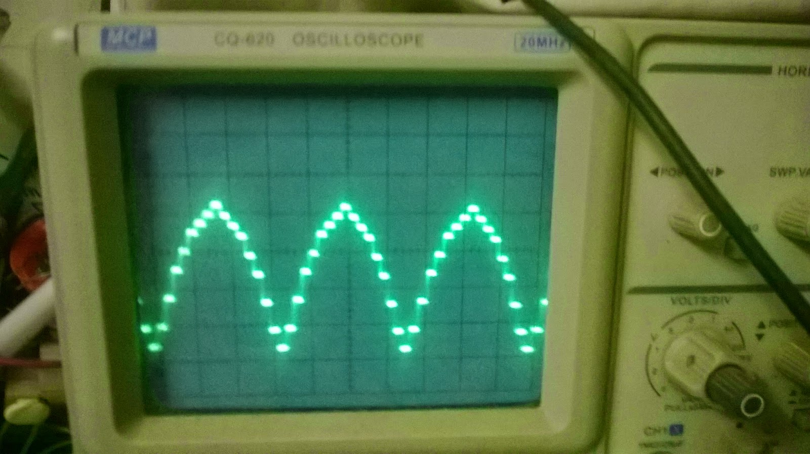
- Sine_1 mode - Generate half sine wave output with 16 point sine table. The 16 DAC points are used for the entire sine half wave. DAC used with 16 steps (see Fig. 3 below)
- Sine_2 mode - Generate half sine wave output with 32 point sine table (16 step DAC mode) - ie this uses the 16 DAC points for half of a sine half wave and then repeats these for the second half, utilizing the 16 step DAC more fully (see Fig. 4 below)
Fig. 1 - Sawtooth mode
Fig. 2 - DAC_Out mode
Fig. 3 - Sine_1 mode
Fig. 4 - Sine_2 mode
Here are download links to the source code:
Source code (main.c):
https://drive.google.com/file/d/0B4SoPFPRNziHZUd5NHM5UDhiSGs/edit?usp=sharing
http://www.4shared.com/file/HaU5syz-ba/main.html
Any ideas? Comments? Feedback? Let me know in the comments section below!


Comments
Post a Comment