Creating Project in Keil Micro Vision
Keil MicroVision is a free software, we use it for embedded program developing. In this software we have provided a platform to write a program using text editor, compile program to convert source code into machine language i.e. compiler will convert source code into hex file.
Here is simple guidance for
- How to write programs in Assembly language or C/C++
- How to Compile and Assembling Programs
- How to Debug program
- Creating Hex and Axf file
- Test a program without Available real Hardware (Simulator Mode)
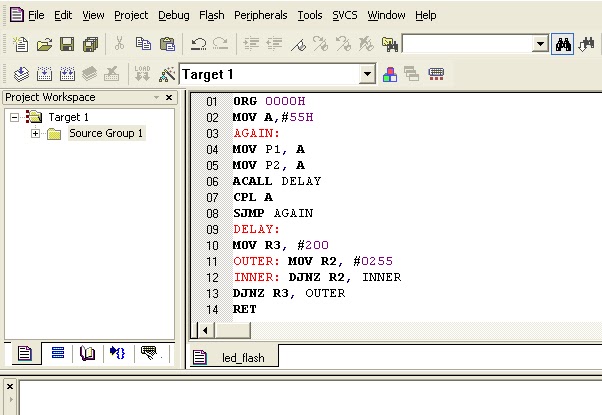
Here a program to write a data 55H to port 1 and complementing data after some time delay is explained. Following is the process of writing program in Keil ,its execution and Debugging :
Step 1: Open Keil uV3

Step 2: After opening Keil uV3, Go to Project tab,create New Project ,select new folder and give name to the Project.

Step 3: After Creating project following window will pop-up. Now Select your device model e.g AT89C51

Step 4: To select device click on left '+' sign in front of Atmel device.

Step 5: Following window will pop-up. Now scroll down and Select your device model e.g AT89C51

Step 6: Following window will pop-up. click on No.

Step 7: Now go to File and create new file, following window will open, this is text editor to write your own code. Write the code in editor and save the it.

Step 8: Save the program using extension '.asm' for assembly language or '.c' for c language.
Step 9: Now Right click on Source Group1 and then add files to Group 'Source Group1'

Step 10: Now Build the Target (compile the program) by clicking on build tab shown by green circle as below: It will give result of compilation in command window shown by red colored square window :

Step 11: Now we can start Debug session using Debug tab after that run the the program using Run tab shown by pink colored circle and check status on peripheral using peripheral tab.We can also check value of general purpose register in project work space under the Register tab

Step 12: If you want to watch waveform on particular port pin or port use Logic analyzer Window and add particular pin or port to the window then you will see waveform on that particular port or port pin as shown below : here waveform on pin port 1.1 shown.


Comments
Post a Comment