Research and Design of Solar Products
SOLAR CHARGE CONTROLLERS


Circuit 1 - On/Off
Circuit 2 - PWM

Circuit 3 - MPPT
While working at Nice Electrical and Electronics Industries Limited as part-time researcher and circuit developer, I have designed Solar Charge Controllers of different capacity (15A to 50A).
The charge controller is controlled by a 16F690 PIC microcontroller. The microcontroller first senses the input voltage from the solar panel. If the voltage is above 12.6V and below 19V, charging takes place.
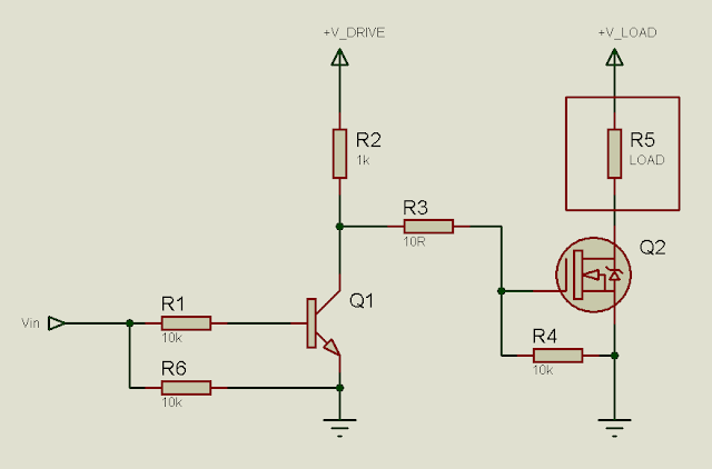
Circuits 1, 2 and 3 share similar hardware but the control methodology is different.
The MOSFET is configured as a high-side switch. A charge-pump circuit is set up that boosts the input voltage to a voltage between 24V and 36V (depending on input voltage). The microcontroller provides the PWM signal to the boost stage. The boosted voltage (between 24V and 36V) is used to drive the high-side MOSFET.
Circuit 1 is simple on/off type series pass charge controller. When voltage is between 12.6V and below 19V, the microcontroller turns on the MOSFET and the voltage from the panel is provided to the battery via the MOSFET. The battery voltage is monitored and when the voltage is above 14V, the charging is stopped until voltage falls below 13.7V.
Circuit 2 is PWM based. The microcontroller generates the PWM signal depending on input voltage. The MOSFET is driven based on the PWM signal and the battery is charged. When the battery reaches 14V, charging is not stopped. Instead, duty cycle of PWM is reduced. This acts like "trickle" charging, to keep the battery fully charged.
Circuit 3 is MPPT (Maximum Power Point Tracking) based. The microcontroller generates the PWM signal and drives the MOSFET accordingly, while adjusting duty cycle to "search" for the maximum power point to maximize charging current. The circuit currently works and charges the battery although the maximum power point tracking isn't great. I am going to have to further work on this circuit to make it perfect.
_________________________________________________________________________________________________________________________
300W 12VDC to 220VAC SMPS-based Solar Inverter


Circuit 1
Circuit 2
While working at Nice Electrical and Electronics Industries Limited as part-time researcher and circuit developer, I also designed Solar Inverters of different capacity.
Circuits 1 and 2 are both DC-AC converters. 12V DC is first stepped up to 240VDC using a push-pull converter. SG3525 generates the PWM signal. The high voltage DC is kept regulated.
In Circuit 1, a 50Hz auxiliary transformer is used for output voltage sensing and the voltage output from the 50Hz auxiliary transformer is fed to the SG3525 which uses it to keep the output voltage constant.
In Circuit 2, a voltage feedback loop is designed using TL431 and opto-coupler, eliminating the need for a 50Hz auxiliary transformer.
The high voltage DC is then converted to AC by a full-bridge stage using 4 MOSFETs. The 50Hz signals are generated by the 16F690 microcontroller. The signals are fed into high-low side MOSFET drivers L6385E using opto-couplers so that the low-voltage side (where the microcontroller is) is isolated from the high-voltage side (where the drivers and MOSFETs are). The drivers drive the MOSFETs according to the signals generated by the microcontroller. The output voltage is kept constant as the high-voltage DC bus is regulated by the SG3525.
The microcontroller also senses the battery voltage and shuts off the inverter when battery voltage falls below 10.8V, providing low-voltage protection. The load current is also sensed by the microcontroller to provide over-load protection.
All MOSFETs are mounted on heatsinks for heat dissipation. The transformer, using ETD39 core, was wound by me as tailor-made wound ferrite transformers are not available in Bangladesh.
The entire circuit from concept to design to implementation was done by me as nothing ready-made is available here!


Comments
Post a Comment