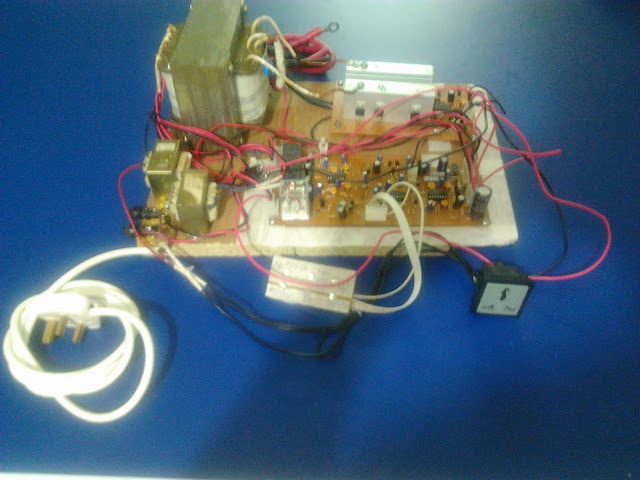
600W 50Hz sine wave inverter test circuit
Here I tested a 600W 50Hz sine wave inverter circuit using push-pull topology instead of full-bridge topology. 2 PIC16F684's were used - one for SPWM and one for charging. 2 microcontrollers were used intentionally as the purpose was to test if I could use the microcontrollers together and use each of them for multitasking. 2 auxiliary transformers are used - one for powering the circuitry when running off mains and one for current sensing. Charging is done with 4 relays that are turned on/off according to input voltage and accordingly connect the input voltage to an appropriate transformer winding/tapping to keep output voltage relatively constant. Switching frequency is 16kHz. The sine table has 32 values.
Here is the complete sine table:
0, 16, 32, 47, 62, 77, 91, 103, 115, 126, 136, 144, 151, 156, 160, 162, 163, 162, 160, 156, 151, 144, 136, 126, 115, 103, 91, 77, 62, 47, 32, 16, //65%
0, 17, 33, 49, 65, 80, 94, 107, 120, 131, 141, 149, 156, 162, 166, 168, 169, 168, 166, 162, 156, 149, 141, 131, 120, 107, 94, 80, 65, 49, 33, 17, //67.5%
0, 17, 34, 51, 67, 82, 97, 111, 124, 135, 146, 154, 162, 167, 172, 174, 175, 174, 172, 167, 162, 154, 146, 135, 124, 111, 97, 82, 67, 51, 34, 17, //70%
0, 18, 35, 53, 69, 85, 101, 115, 128, 140, 150, 160, 167, 173, 178, 180, 181, 180, 178, 173, 167, 160, 150, 140, 128, 115, 101, 85, 69, 53, 35, 18, //72.5%
0, 18, 37, 55, 72, 89, 104, 119, 133, 145, 156, 166, 174, 180, 184, 187, 188, 187, 184, 180, 174, 166, 156, 145, 133, 119, 104, 89, 72, 55, 37, 18, //75%
0, 19, 38, 56, 74, 91, 108, 123, 137, 150, 161, 171, 179, 186, 190, 193, 194, 193, 190, 186, 179, 171, 161, 150, 137, 123, 108, 91, 74, 56, 38, 19, //77.5%
0, 20, 39, 58, 77, 94, 111, 127, 141, 155, 166, 176, 185, 191, 196, 199, 200, 199, 196, 191, 185, 176, 166, 155, 141, 127, 111, 94, 77, 58, 39, 20, //80%
0, 20, 40, 60, 79, 97, 114, 131, 146, 159, 171, 182, 190, 197, 202, 205, 206, 205, 202, 197, 190, 182, 171, 159, 146, 131, 114, 97, 79, 60, 40, 20, //82.5%
0, 21, 42, 62, 82, 100, 118, 135, 151, 165, 177, 188, 197, 204, 209, 212, 213, 212, 209, 204, 197, 188, 177, 165, 151, 135, 118, 100, 82, 62, 42, 21, //85
0, 21, 43, 64, 84, 103, 122, 139, 155, 169, 182, 193, 202, 210, 215, 218, 219, 218, 215, 210, 202, 193, 182, 169, 155, 139, 122, 103, 84, 64, 43, 21, //87.5%
0, 22, 44, 65, 86, 106, 125, 143, 159, 174, 187, 198, 208, 215, 221, 224, 225, 224, 221, 215, 208, 198, 187, 174, 159, 143, 125, 106, 86, 65, 44, 22, //90%
0, 23, 45, 67, 88, 109, 128, 147, 163, 179, 192, 204, 213, 221, 227, 230, 231, 230, 227, 221, 213, 204, 192, 179, 163, 147, 128, 109, 88, 67, 45, 23, //92.5%
0, 23, 46, 69, 91, 112, 132, 151, 168, 184, 198, 210, 220, 228, 233, 237, 238, 237, 233, 228, 220, 210, 198, 184, 168, 151, 132, 112, 91, 69, 46, 23 //95%
//0, 25, 49, 73, 96, 118, 139, 159, 177, 193, 208, 220, 231, 239, 245, 249, 250, 249, 245, 239, 231, 220, 208, 193, 177, 159, 139, 118, 96, 73, 49, 25, //100%
Each 32 values corresponds to one half-cycle of a 50Hz sine wave, each set corresponding to a different duty cycle. The duty cycle varies as the amplitude of the sine wave is varied by adjusting the value of the CCPR1L register. The maximum value of each set of 32 values is set to correspond to a different duty cycle and the other 31 values are in the same ratio to the maximum value for all sets of values. A pointer is used in the main code to retrieve the required set of 32 values for a required duty cycle. The lowest duty cycle is 65% because, for feedback, lower duty cycles are not required. The maximum duty cycle is set at 95% to provide some dead-time and avoid cross-conduction. At the beginning of each half-cycle, one MOSFET is driven according to the duty cycle values retrieved from the table. At the end of the half-cycle and beginning of the next half-cycle, the other MOSFET is driven according to those same duty cycle values. Upon a fault condition (such as low-battery), both MOSFETs are turned off and kept off.
It works as intended and testing was successful. However, it requires adjustments to be made for the final one.


Comments
Post a Comment