NE555 Example Project: Light detector
NE555 Operation
The NE555 comprises 23 transistors, two diodes 16 and resistors which form four elements:- two operational amplifiers Compare type;
- an inverter logic gate;
- SET and RESET latch.
The NE555 can operate in three modes: monostable, astable or bistable. I will detail precisely two in this article, the third being extremely simple.
Astable operation
For me, this is the simplest operation. This configuration allows to use the 555 as oscillator which will generate a square wave signal at its output. The astable word means that the timer has no stable state.
The resistors Ra and Rb and capacitor C can modify the oscillation frequency and cylique report (have a look on the net if you want to know what these terms, they are important enough to the operation of this IC) .
A complete oscillation is performed when the capacitor charges to 2/3 Vcc and discharged at 1/3 Vcc (voltage applied to the input of 555). During charging, the resistors Ra and Rb are in series with the capacitor, but the discharge is carried out only through Rb. It is in this way that the duty cycle can be changed.
 |
| The signal emitted by the NE555 in astable configuration |
Monostable
Monostable configuration 555 to generate a pulse of duration just defined (the signal is not symmetrical) with a single resistor R and a capacitor. The shot term means that the timer has only one state that is stable.
A pulse is generated following the application of a falling edge at the circuit input (TRIG), the graph below shows the resulting wave forms.
Immediately after application of the falling edge, the internal flip-flop and the output are enabled. At the same time, the discharge transistor is turned off allowing the capacitor C to charge through the resistor R. The waveform across the capacitor is that of a first-order RC facing a voltage level, c that is to say an increasing exponential. When this exponential reaches a value equal to two-thirds of the supply voltage Vcc, the internal toggle is off reducing the output and the capacitor to zero.
 |
| The signal emitted by the NE555 monostable configuration |
Bistable operation
I will not dwell on this mode of operation because of its simplicity. The bistable term means that the timer has two stable states, 0 and 1. The transition from one state to another can only take place with the aid of an external action such as the actuation of a button. The flip-flop is an example of bistable electronic component. |
| The signal emitted by the NE555 bistable configuration. |
Light detector using NE555
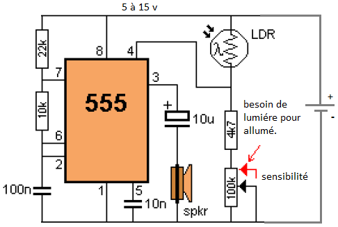 |
| Light detector using NE555 |
This circuit detects the light falling on the photocell (LDR) to turn the NE555 and create a tone that is delivered to the speaker. Pin 4 must be kept below 0.7V to turn off NE555. Any greater than 0.7V voltage will activate the circuit. The adjustable sensitivity control is necessary to define the level at which the circuit is activated.
When the substrate sensitivity is turned so that it has the lowest resistance (as shown in red), a large amount of light to be detected by the
LDR its resistance is low. Thus, a voltage divider composed of resistor LDR and 4k7 (4.7 kilo ohms). As the resistance of the LDR decreases, the voltage across the 4K7 increases and the circuit is activated.
When the control sensitivity is taken on the 0V rail, its resistance increases and this effectively adds resistance 4k7. The lower part of the voltage divider now has a greater resistance and it is in series with the LDR. Less light is needed.


Good points about smps. It is very important part of the computer. Thanks for details. We are into computer and hp laptop service and it is very useful for me and our service team.
ReplyDeleteSMPS and the fan unit should be cleaned regularly. If it gets stuck up then it can cause problem to the pc. Very good points about smps repairing. Keep updating more. Thanks.
ReplyDelete