Posts

Showing posts from November, 2016

New XP Embedded tutorial videos now available!

Hey all, some folks on the XP Embedded team have recorded some video demonstrations of various features of XP Embedded, including walkthroughs of some of the new XPE SP2 features.  Click here to check them out today!  I did the Device Update Agent (DUA) video, so please forgive me for being a little nervous.  I also had a really bad cold the day I recorded it and had to stop for some coughing fits, but the folks in the MSDN recording studio did a great job of editing it out  🙂  Here's a complete list of the videos that are available (not all of them are new): Accelerated Operating System Configuration Automated Dependency Checking and Build Process Building a Windows XP Embedded Device Device Update Agent for Windows XP Embedded Windows Embedded Application Development Windows XP Embedded – Basic Lab Windows XP Embedded Product Overview Windows XP Embedded with Service Pack 2 – Basic Windows XP Embedded with Service Pack 2 Technical Training: Embedded Enabling

Embedded Tutorial on Low Power Test

Unlimited reading Read as many articles as you need. Full articles with original layout, charts and figures. Read online, from anywhere. Stay up to date Keep up with your field with Personalized Recommendations and Follow Journals to get automatic updates. Organize your research It's easy to organize your research with our built-in tools.

HOW TO USE 8051

Simulating and debugging your micro-controller project is fun on a computer using Proteus or similar software but when it comes to practical implementation, it's a bit complicated, or I would say "a headache", to get things done. Its not as simple as mounting the IC on bread board and expecting some output straight away. You have to take care of the "protocols" to achieve your target. You must provide the micro-controller unit (MCU) with proper connections for proper start-up and output. UPDATE: Visit this link for an updated version of this post - with more details and insight. READ MORE

Research on transformerless AC-AC (sine wave) conversion- Part 1: AC-AC Buck

Image
In Bangladesh, mains AC line voltage may vary quite a lot, sometimes down to about 180V (or maybe lower!) and sometimes up above 220V. Thus, using a voltage regulator/stabilizer is necessary so that the output voltage is fixed, if not exactly at 220V, somewhere around that. 210-225V is an acceptable range. The common method of AC-AC voltage regulation/stabilization is to use relays to switch the AC input voltage into different tappings of a transformer, so that the voltage is stepped up or down by an amount, as required, depending on the input voltage. There are 2 things in this circuit that could be improved: 1) Output voltage variation - Output voltage may sometimes vary by 10V or maybe even up to 20V. While, in most cases, it may be acceptable, a tighter regulation would certainly be better. 2) Cost - This type of stabilizer becomes quite expensive due to the large 50Hz transformer required. Also labor costs are high due to winding transformer with multiple tappings. So, for the las

Feedback in sine wave inverter (PIC16F series based)

I have previously shown how to calculate the values for the sine table: http://electel.blogspot.com/2016/01/generation-and-implementation-of-sine.html I have also shown how to implement SPWM in PIC16: http://electel.blogspot.com/2016/10/generation-of-sine-wave-using-spwm-in_10.html Now I will show how to implement feedback for SPWM. Due to various limitations in PIC16, such as ADC speed, instruction time and the ALU, it is extremely difficult, if not impossible, to calculate in real time the values required for feedback in sinusoidal pulse width modulation (SPWM). Thus, to implement feedback, a different approach must be used. That approach would be to retrieve the values from a sine table that contains the duty cycle values for a specific duty cycle. Here is one sine table I used, for example: const unsigned char sin_table[416]={ 0, 16, 32, 47, 62, 77, 91, 103, 115, 126, 136, 144, 151, 156, 160, 162, 163, 162, 160, 156, 151, 144, 136, 126, 115, 103, 91, 77, 62, 47, 32, 16, //6

Introduction to the PIC32 - The Basics, Getting Started, IO ports and the First Program

View on Scribd View in Google Docs Download PDF (4shared)

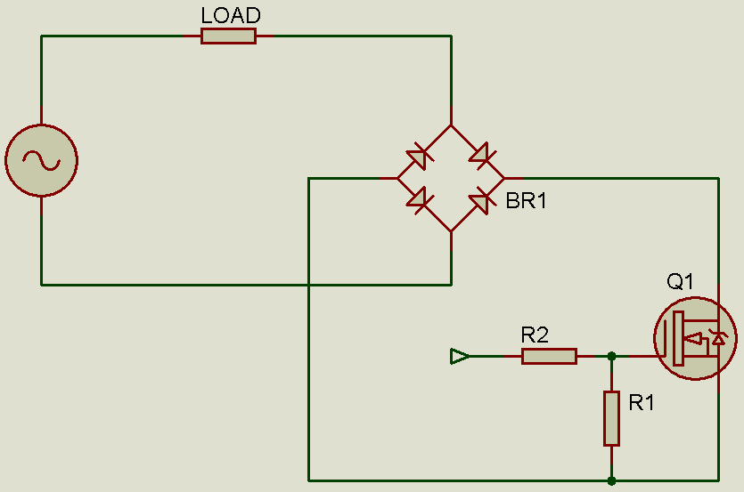
Controlling an AC load with a MOSFET

Image
In most cases where you want to control an AC load, a triac or SCRs will be used. However, it is not easy to drive a triac or SCR. The drive requirement for the triac or SCR makes it sometimes difficult to control it as we want. One thing is that we can not turn the triac or SCR on or off as we desire, because once we turn it on, it latches and stays on until the next zero crossing or until current stops flowing through it. Also, driving a triac with reference to MT1 (or A1) is not as straightforward as we would want. However, a MOSFET can be controlled as we want. Set the gate high (with a sufficient voltage) and current can flow from drain to source. Set the gate low and current can no longer flow. Convenient! However, a MOSFET can only be used to control DC loads since it is a unidirectional switch - current flow can be controlled when it is flowing from drain to source, but can not be controlled from source to drain. So, certainly it can not be used to control AC loads. Right? Well

DC motor control with PIC16F877A - Practical example of PIC PWM

Image
We all know what a motor is and what it does. The simplest way to run a motor is to just connect it to a power source. For a DC motor, that would mean, just connecting the motor to the DC voltage that the motor was rated for (or less). But, can you control the speed? Yes. The simplest method is to control the speed of the motor by controlling the voltage the motor runs off. Imagine we have a 12V motor. If you run it off 12V, you get maximum speed (you can get more at higher voltage, but let's not go over rated specifications!). So, simple logic dictates that as we decrease the voltage to the motor, the speed must decrease. You can use a simple LM317 regulator to adjust the voltage to the motor and thus the speed. But, this method of speed control has one huge disadvantage - inefficiency when using a linear regulator (and you may find the motor not running at all at lower voltages). Let's talk about the inefficiency. If we use a linear regulator to give 6V output f