Research on transformerless AC-AC (sine wave) conversion- Part 1: AC-AC Buck
In Bangladesh, mains AC line voltage may vary quite a lot, sometimes down to about 180V (or maybe lower!) and sometimes up above 220V. Thus, using a voltage regulator/stabilizer is necessary so that the output voltage is fixed, if not exactly at 220V, somewhere around that. 210-225V is an acceptable range. The common method of AC-AC voltage regulation/stabilization is to use relays to switch the AC input voltage into different tappings of a transformer, so that the voltage is stepped up or down by an amount, as required, depending on the input voltage.
There are 2 things in this circuit that could be improved:
1) Output voltage variation - Output voltage may sometimes vary by 10V or maybe even up to 20V. While, in most cases, it may be acceptable, a tighter regulation would certainly be better.
2) Cost - This type of stabilizer becomes quite expensive due to the large 50Hz transformer required. Also labor costs are high due to winding transformer with multiple tappings.
So, for the last six months, I have been researching on AC-AC "transformerless" converters, attempting to convert the line voltage to provide an output voltage either higher or lower than the input voltage, as required. If input voltage is lower than required (the reference voltage is approximately 220VAC), then the voltage is stepped up. If input voltage is higher than required (the reference voltage is approximately 220VAC), the voltage is stepped down. However, I've been trying to do this without the use of any 50Hz transformer, which is quite bulky, large and expensive.
My first idea was to first convert the line voltage to DC, step it up and then use SPWM (sinusoidal pulse width modulation) on a MOSFET with feedback to provide a sine wave output with the required voltage (approximately 220VAC).
However, I thought, there must be a simpler way. There must be a way to control the line AC without having to convert to DC. There must be a way to achieve regulation without the use of 5 MOSFETs.
Then, I thought of the buck-boost converter. If it could be done on DC, it can also be done on AC.
But that was the problem. How would it be done on AC? I would need a high voltage high frequency device - a high frequency high voltage switch that I can control with a microcontroller. In the DC-DC buck-boost converters, MOSFETs and diodes are used with DC. But, they can not be used in the same way with AC since direction of current is alternating and I can not directly control the flow of AC with a single MOSFET.
So, I decided to break it up. Instead of attempting to construct the DC-DC buck-boost converter at once, I thought of first constructing the buck converter to test it out to see if my idea of direct line voltage control was correct.
I analyzed the DC-DC buck converter so that I could make a similar circuit for AC: an AC-AC buck converter.
Here is the DC-DC buck converter (the switch can be a BJT, MOSFET or IGBT):

Here, you can see the current flow when the switch is on:

Here, you can see the current flow when the switch is off:

If you are not clear about how buck converters work, you should read up on them. Many tutorials can be found online and there are many books on SMPS available. These are 3 of the books I learnt from (and they're great books):
Power Supply Cookbook - Marty Brown
Switching Power Supplies Demystified - Raymond Mack Jr
Switching Power Supply Design - Abraham Pressman
I started thinking about porting the same DC-DC buck concept for AC-AC buck converter. The switch could no longer be a single BJT, MOSFET or IGBT as they are unidirectional switches (can control flow of current in only one direction) and so can not be used for AC. The diode also needed to be replaced with a switch that would be turned on when the main switch was off, and vice versa. Why? Because in the DC-DC buck converter, direction of flow of current when the switch is off will be the same at all times. However, in an AC-AC buck converter, direction of flow of current will alternate every half cycle. So, one half cycle, the diode would be forward biased, but the next half cycle, it would be reverse biased.
So, here is the AC-AC buck converter circuit:

Notice how the diode is now replaced with a switch - SW2. Also, notice how no electrolytic capacitor is used at the output. The reason is obvious - the output is AC, so we can not use a capacitor that has polarity.
If you have understood how a buck converter works, the next 4 diagrams showing the flow of current should be self-explanatory in demonstrating an AC-AC buck converter.
Current flow when SW1 is on in the positive half cycle:

Current flow when SW1 is off in the positive half cycle:

Current flow when SW1 is on in the negative half cycle:

Current flow when SW1 is off in the negative half cycle:

That seemed reasonable - it should work, I thought. But, what would I use for SW1 and SW2. I can't use triacs since they're too slow and there's no way they can be used with frequencies of tens of kiloHertz. Plus, they would just latch on when fired. So, I had to somehow use MOSFET(s) or IGBT(s). But how?
Well, with some clever circuitry, it's possible to control AC loads with MOSFETs/IGBTs. And I showed how here: http://electel.blogspot.com/2016/11/controlling-ac-load-with-mosfet.html
For convenience, I'll summarize it here.
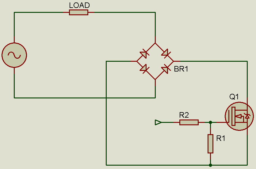
Perhaps you don't see how it works now. But consider the two diagrams below, which show the flow of current during the two AC half cycles. I'm sure you'll get it better then.


As you can see, due to the bridge rectifier, the MOSFET always "sees" a DC voltage as the drain is always positive with respect to the source. Thus, with this combination of the bridge rectifier and MOSFET, by controlling a DC switch - the MOSFET, you can control the AC current flow.
So, I could replace SW1 with a bridge rectifier and MOSFET, and SW2 with another bridge rectifier and MOSFET.
Initially when testing, I hadn't included SW2 and found that it caused the inductor to saturate. After a few seconds, volt-time averaging wasn't happening. This is because the inductor's flux is not "reset" and it just stores the energy which is not dissipated when SW1 is off.
Then, I included SW2 and everything worked well. There was no more problem. You must remember that since frequency of operation is 20kHz, a normal bridge rectifier can not be used. For the bridge rectifier, ultrafast diodes must be used.
Now comes the part about control - how to control the voltage.
In the AC-AC buck circuit, SW2 acts like the diode in a DC-DC buck converter. So, our buck conversion and chopping is done by SW1.
In a DC-DC buck converter, the output voltage is given by:
Vout = Vin * DC [where DC = Duty Cycle]
So, if duty cycle is 50% or 0.5, the output voltage is half the input voltage.
Is that also correct for AC-AC buck converter? It should be, since it uses the same principle. And, yes, it is.
Here's the principle of operation:
A microcontroller (I used PIC16F684) detects zero-crossing. Upon zero-crossing, PWM is started. The selected frequency is 20kHz. It's the maximum frequency I can get with a PIC16F684. Let's take an example with 50% duty cycle. So time period is 50us. Every cycle (20kHz, not the 50Hz one), SW1 is kept on for 50% of the time. So, for 25us, SW1 is kept on. Then, SW1 is turned off. A small deadtime is provided and SW2 is kept on for the remainder of the cycle to act as the catch diode. At the end of the cycle another dead time is provided before SW1 is turned on. The deadtime (or deadband delay) is provided so that SW1 and SW2 aren't on at the same time.
So, what happens is, the 50Hz AC wave is broken down into 400 parts and pulse width modulation is carried out over each part. Each part represents a time of 50us. So, when half of each of the 400 parts is kept on and the other half is kept off, due to the LC filter which will do the volt-time average, you will get a sine wave output - the same waveshape as that of the input - but with half the amplitude. So, the input AC voltage has become halved in amplitude, without a distortion of the waveshape. The duty cycle can be varied to obtain other voltages.
These 2 diagrams illustrate the above example:

Signal from microcontroller (in red)

Chopped Input Voltage (in red)
Filtered Output Voltage (in blue)
These 3 diagrams should clear your doubts:


In the AC-AC buck converter, feedback is implemented. The microcontroller senses the output voltage and increses or decreases the duty cycle to adjust the output voltage as required, to deal with line/load variations.
Here is the prototype at work (generating an output voltage of 115VAC from 230VAC input):

The output waveform without proper filtering:

The output waveform with proper filtering (the "jerkiness" of the waveform is due to the slow response of the camera sensor):

So, I've shown and explained AC-AC buck conversion. In the next part (part 2), I will show and explain the boost part. With the buck and boost parts combined, a transformless AC-AC converter can be created, which when controlled precisely by the microcontoller, can scale the line voltage up or down without having to regenerate the sine wave, thus outputting a wave that has a different amplitude but same waveform as that of the input wave.
My research on this topic is still going on and once I am done, I will post part 2 of my research (boost conversion) on transformerless AC-AC (sine wave) conversion.


Comments
Post a Comment