Single microcontroller based 12v to 230v inverter with intelligent battery charging
Here I describe the circuit as:
*single microcontroller/controller (ATMEGA16/32)
*no op-amps, only chips are the micro, opto-couplers and regulator (7805)
*low-battery/overload/short-circuit protection
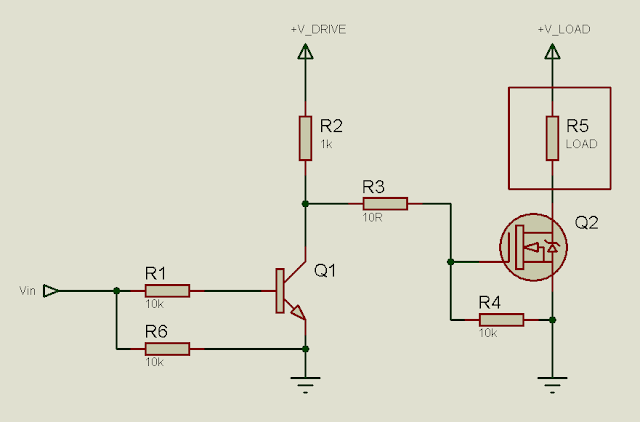
*thyristor controlled battery charger, using the MOSFET body diode as the AC-DC rectifier
*charger maintains the battery voltage (top) between 13.2-13.5v (adjustable) to maximize the battery life
*6-LED display
*Only 93 parts in entire control circuit
*Delay between switchover to prevent inrush current
The method used here, described for those who may benefit from it:
-Initialize all ports and peripherals[ADC, Timers, Compare Modules]
-Initialize interrupts for Timer0 and compare module for
-For PWM, use Timer1 and 16-bit Phase and Frequency Correct PWM mode so the PWM runs completely on the hardware level without need for interaction to keep it running
-The AVR senses whether mains is present or not using a standard opto (4N35).
-If mains present, check battery level
-If battery level < 13.5v (this voltage is set using a pot, so can be easily adjusted), charge at the set current(set with a pot)
-If battery level > 13.5v, stop charging
-While battery > 13.2v, stop charging
-If battery voltage drops instantly start charging again
-Triac based, uses Timer0 and compare module with interrupt for phase angle control for fast charge, never overcharges battery, battery hasn't ever heated up till now and 2 year old battery still gives good backup, so charging algorithm is good for battery life
-Check mains
-If mains absent, initialize Timer and start PWM
-Check battery voltage, stop PWM and indicate on LED when battery falls below 10.8v (this is also set with a pot), response time is fast so a short circuit that produces an instant voltage drop is detected
-Check load level, check against preset level (set with pot) and if too high, shut down and indicate
-Check output voltage, adjust as required
-Check mains
*Coding is done with mikroBASIC PRO for AVR
*All voltages mentioned, eg 13.2v, 13.5v, 10.8v, Overload voltage, etc are all adjustable and set with variable resistors


This is a quasi-sine wave inverter that I made since it was more demanding than the sine at the time. I have a project with sine as well with a PIC but it's not very organized.
IPS stands for "Intelligent Power Supply", in short the inverter. IPS on means inverter on.
No, they're power MOSFETs. The design here uses IRFZ44N x 5 on each leg for 800W. You can use other MOSFETs as well. I haven't tried though. There are 4 transistors for driving the MOSFETs, on the control board - 2xPN2222, 2xPN2907. There are 2 more transistors on the MOSFET board.
It's 12-30v with changing resistors. For upto 48v, you need to change the 7805 with an auxilary supply, that's the only change.
If battery increases while charging, then there is battery full charged indicator.
Output volt is adjusted to achieve 230V or 220V as required, that is for feedback voltage setting or output voltage setting when running in inverter mode. I set mine at 230V.
Battery max is for battery high cut voltage, to cut off charging when battery reaches a specific voltage. I set mine at around 13.5v.
Charging current is for setting the current at which battery is to be charged. I set mine for 12-15A for 70Ah battery for quick charge.
Overload is for setting the maximum load. A load (800W in this case) is applied while running in inverter mode, and the pot is adjusted slowly till at one point the inverter turns off and the LED shows overload.
Low battery is for setting battery low cut voltage. I set mine for 10.5v.
On the board, the pots are labeled "HI CUT, LO CUT, OVERLOAD, FEEDBACK, CHARGING CURRENT". The one for current is a pot that is adjustable in small units.
The 4 transistors are for MOSFET driving, the other 2 are for fan and relay.
There are 2 optocouplers, one for mains sense, the other for zero crossing detection. (If you are interested in zero-crossing detection, go through this: http://electel.blogspot.com/2016/10/zero-crossing-detection-with-pic16f877a.html
I forgot to mention, this circuit requires NO AUXILIARY 9-12V TRANSFORMER.
The transformer I have is 12-0-12 primary, doesn't need to be accurate, since you can adjust the output voltage using the pot. What I meant is, say you wanted a 12-0-12 transformer, but you got some error, then you can just adjust the preset/pot to set output at 230v. No separate winding, feedback is done on board using diode/cap/resistor and micro. Charging is done using the same MOSFET board, no special capacitor or inductor, just a snubber on the board. Transformer primary is not strict. The one I used has 12-0-12 primary, secondary 0-140-280. 140 is the charger tapping, 280 is the output voltage that is adjusted.
In my circuit, I've tested it numerous time and micro never misfired. Moreover, if you notice the board, you should say a hell lot of .1u ceramic caps, ie, 104pF caps. So since decoupling is so well done, I don't think there will be firing problems. A snubber may be added IF NECESSARY. I've found that the snubber isn't always necessary and gets very hot, so I omitted it, however it may be necessary in some situations so could be added there. This is also one reason I used BTA26, huge triac so that it isn't usually shorted by other factors as I know heat and firing are not issues. All in all, this seems reliable and has run over the last few months under numerous tests.
Yes, MOSFET can be added for a nice design, but I omitted it as it was more demanding to have the MOSFET board separate, in case the MOSFETs burnt. Haven't had a situation till now, but it can easily be made into one nice PCB.
The transformer is rated at 800W power and is a standard transformer used for 800W inverters over here. I don't know about the details as I got it wound by an acquaintance who is an expert in making such transformers. The primary voltage is 12-0-12, secondary voltage is 0-140-280.
This inverter has short circuit protection. It uses the fact that during a short circuit, DC bus voltage significantly decreases. The microcontroller senses that and indicates short circuit.
Reverse voltage protection isn't provided as it's connected to the battery 24/7.
Yes, the battery charging part. My one isn't as complicated. It's a simple charger that doesn't charge the battery to absolutely full charge, but maximum charge so that it can provide optimum backup and good battery life.
The battery is charged at around 16A when near full discharged and charge current slowly decreases to about 10A when battery is near 13.5v, when battery charging is completely terminated to prevent gassing or oxidizing of the plates.
The battery charging is phase angle control based and the charging is stopped every 13 seconds when battery voltage is checked. Then charging is resumed again. I initially implemented trickle charging but later discarded it as I found it unnecessary in this case, because whenever battery voltage falls charging is again resumed for a few minutes to make sure battery is fully charged, or at least apparently fully charged.
I've had the test unit running for 8 months, but the final version as shown in the pictures has been running for about 6 months. The battery has never become hot. Moreover, it was about a year old when I started using this inverter. The battery hasn't inflated yet and provides good backup. I don't even have to replace the water frequently, so that shows that the water isn't vaporizing.
I'm using a 12v 70Ah battery. As mentioned earlier, I can run a 40W fluorescent lamp, 80W ceiling fan and computer (around 250W when not at 100% load) for about 2 hours before the unit indicates low battery. From there it takes about 6-7 hours to fully charge the battery and the charging termination to become stable. Usually after running the inverter with 80W fan and 40W lamp, it takes an hour to get it to full charge.
The unit is designed for 150-250v.
The charging current changes with battery rating. The values mentioned are for 70A battery with initial charging current set manually.
I will upload schematic and PCB soon.


Comments
Post a Comment