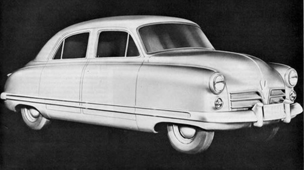
Early Postwar Chevrolet Cadet Project
Below are those images plus a view of a 1949 Chevrolet, GM's post- World War 2 A-Body redesign.
It's hard to tell if this is an airbrush styling rendering or a heavily retouched photo of a Cadet mockup. My guess is that it's the latter because a mockup existed, and in those days General Motors staff produced many retouched images. I further suspect that the grille design was a provisional placeholder for a different production design, though this design would have been satisfactory. Interesting that the grille of the 1953 Studebaker line also has a V'd segment splitter and a single central horizontal bar.
Here is a 1949 Chevrolet four-door notchback sedan. Note that the passenger compartment appears to be almost the same as that of the Cadet -- the Cadet's windshield is one-piece and slightly taller and the beltline falls off more towards the rear. This makes economic sense, as GM could then use most of the same body structure on both cars. The main differences are the nose and rear clips.
Side view of a mockup. During the very late 1930 and early 1940s American styling fashion for cars of the future assumed slab fender sides and covered wheel openings, the latter for aerodynamic (as opposed to practical) considerations.
Power train and suspension layout with seating sketched in. Here the roofline is less flat than that of the production Chevy shown above, though this might have been modified had a production go-ahead happened.


Comments
Post a Comment