Posts

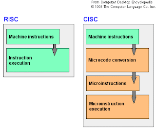
Understanding Processor Architecture: RISC versus CISC
Image
Popular processor designs can be broadly divided into two categories: Complex Instruction Set Computers (CISC) and Reduced Instruction Set Computers (RISC). The dominant processor in the PC market, Pentium, belongs to the CISC category. However, the recent trend is to use the RISC designs. Even Intel has moved from CISC to RISC design for their 64-bit processor. RISC vs. CISC: What is the differences?

Understanding Processor Architecture: Machine and Assembly Language

Image
The processor understands only the machine language, whose instructions consist of strings of 1s and 0s. Machine language is closely related to the assembly language. We prefer to use the assembly language rather than the machine language. Programming in the assembly language also requires knowledge about the processor architecture. Assembly language programming is referred to low-level programming because each assembly language instruction performs a much lower-level task compared to an instruction in a high-level language. Assembly language instructions are processor specification dependents. For example, a program written in the Intel assembly language cannot be executed on the PowerPC processor.

[Tutorial] Making PIANO KEYBOARD with LM555 IC

Image
Hi everyone, today I will guide you how to make a powerful piano keyboard with LM555 IC . OK let's go! Piano keyboard description Here we will show how to build a piano keyboard which generate simple electronic keyboard musical notes DO, RE, MI, FA, SOL, LA, SI, DO1 and RE1, as shown in the following diagram (keyboard piano). Piano Keyboard with IC LM555

ANALOG to DIGITAL CONVERTER with IC ADC0804

Image
Description of ADC The ADC are analog to digital converters have a variety of applications as an intermediate device that converts analog signals to digital form. These signals are used to be digitized for processing digital processors. For example we found a wide variety of sensors that convert the physical characteristics of the sensor into analog signals such as heart rate, temperature, pressure, force, distance, etc. The ADC0804 The ADC0804 is a converter from analog to digital 8 bits. This ADC0804 has only one analog input channel with a digital output eight bits that can mostra 256 values ​​of different measures. The step size is adjusted by setting the reference voltage in pin9 the reference input voltage can be adjusted to allow encoding any smaller range for the entire 8-bit resolution analog voltage. When the voltage reference pin is not connected to the ADC0804, the reference voltage defaults to the operating voltage, ie, Vcc. The step size is 19.53mV 5V (5V / 255),...

[Tutorial] Making a Digital Counter Up 0 to 9 using IC 7490

Image
Description counter 0-9 This counter 0-9 in easy to assemble, basic to use for other more complex where we make use of integrated circuits didactically as these could be replaced by other more complex circuits with simple application of microcontrollers. Counter operation 0-9. This counter circuit is formed by a generator essentially comprises a wave 555 which functions as a circuit astable multivibrator operating this type is characterized by an output square waveform with width defined by the designer.The outgoing wave frequency can be controlled by the resistor is connected between pins 7-8 and 2-7 in addition to the electrolytic capacitor connected to pin 2 of land. The pulse output can be varied by 100K ohm potentiometer (RV1). Circuit counter

[Tutorial] A Small Digital Electronic Project

Image
Small projects of digital electronics are an affordable option for students, teachers and parents as they do not require expensive laboratory and fully stocked. Many young people want to learn about digital electronics and build their own devices as well as work with the parts of a computer and analyze how the circuits of the digital world work, but can not do in their classrooms or at home because it is too expensive. There are several small projects that enable young people to practice the skills necessary to enter college skills, although they are more easily and used parts are readily available.

Turn off Led using PIC16f877a with Assembler Code

Image
Start making a simple program in which we in assembly code using PIC 16F877A to turn on and off an LED by pressing a button as shown in the diagram. We will use two ports of the PIC 16F877A, port B and port D, declare the B port as input and the D port will be configured as an output. In the graph we can see that the pin RB0 is set button and a resistor in a pull-up configuration, when you are not pressing the button it gets a high (5V) to the RB0 input and when pressed he gets a level low (0V). In the output RD0 to turn on the led its output should be at a low level so when developing the program in assembler we test the pin B0 and if a high level put a high value on the output RD0 that will keep off LED, otherwise put a low value on the output RD0 which will cause the LED lights.