Posts

Interfacing a color TFT display with the PIC32MX250F128B

Image
I have been working on interfacing the PIC32MX250F128B with a small 2.2" TFT display from Adafruit. It's a nice little display that is fairly easy to communicate with, using SPI communication. The display I'm using is: http://www.adafruit.com/product/1480 Adafruit provides nice open-source libraries for their products. However, they are for Arduino and thus cannot be directly reused for the PIC32. I went through the library and ported it over for the PIC32, in C. I have attached my project file as a .zip file and you can download it to go through the library header and source files, as well as the demo code. I've tried heavily commenting the code so that it is self-explanatory. As far as hardware goes, with the demo code, the pin connections for the display are: BL (backlight): I left it unconnected, but you can connect it to 3.3V for backlight. SCK: connected to RB14 on the PIC MISO: left unconnected, since I'm not reading anything from the screen MOSI: connected ...

Image

Zero crossing detection with PIC16F877A

Image
Zero crossing detection is very important, especially in power control circuits employing thyristors. I have come across many people struggling with zero crossing detection with PIC microcontroller and thus they cannot fire triacs or SCRs as required. So, here I have explained a simple method of detecting zero crossing with PIC16F877A, employing only two or three resistors, a bridge rectifier and an optocoupler for the hardware portion of zero cross detection.  The PIC 16F877A detects the zero crossing using the RB0/INT external interrupt function. I have explained how the zero cross is detected and how the PIC acts upon detection, below.   Fig. 1 - Schematic, zero crossing signal and RD0 signals --------------------------------------------------------------------------------------------------------- Here is the code for PIC16F877A: (You can download the source file from https://rapidshare.com/files/604474700/ZeroCrossing.c ) -------------------------------------------------...

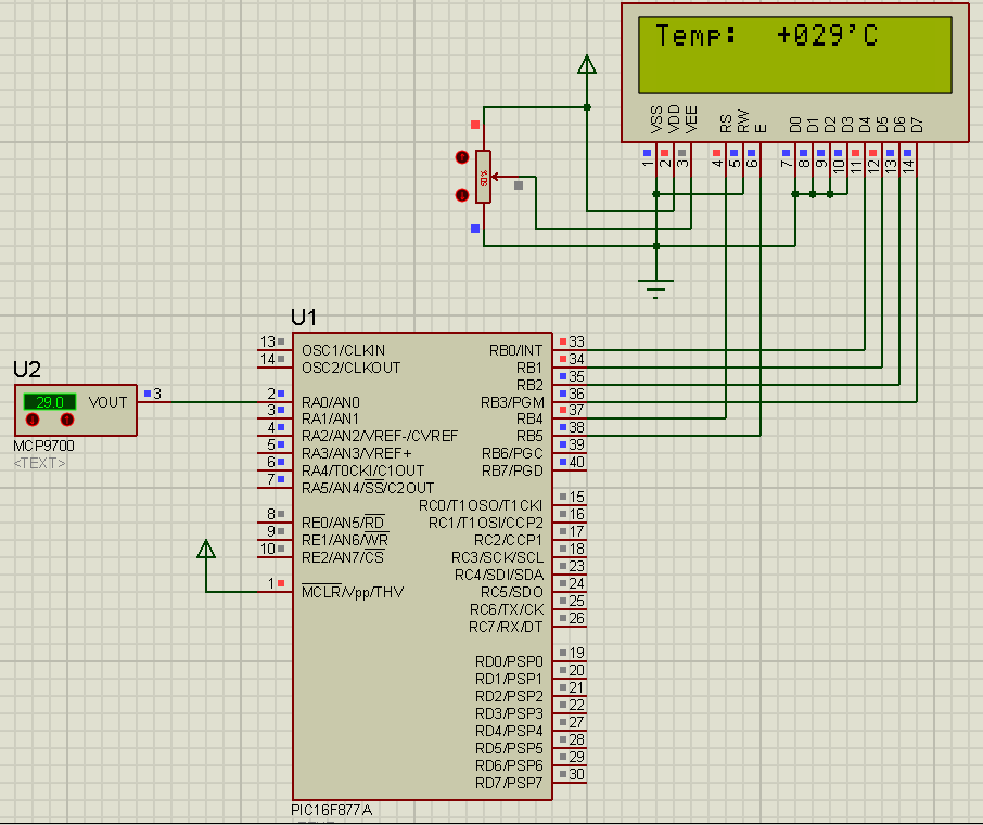
Temperature Sensor (MCP9700 + PIC16F877A)

Image
Here's a temperature sensor (thermometer) circuit that you can easily build. It uses the popular PIC 16F877A microcontroller. The temperature sensor is MCP9700. The MCP9700 outputs an analog voltage corresponding to the temperature. The PIC reads the analog voltage, processes it and displays temperature on the LCD. The temperature range of this circuit is -40'C to +125'C. The methods of processing the output of the MCP9700 can be found in the datasheet: ww1.microchip.com/downloads/en/devicedoc/21942a.pdf  The analog to digital conversion is done by the PIC ADC module. In the code, I've used the mikroC library function for ADC. You can view the library file here: http://www.mikroe.com/download/eng/documents/compilers/mikroc/pro/pic/help/adc_library.htm However, you should have a knowledge of how the ADC module works and how to use it. I had written a tutorial on modalities of operation of the PIC 16F877A ADC. You can find the tutorial here: http://electel.blogspot...

Temperature Sensor (DS18S20 + PIC16F877A)

Image
Here's a temperature sensor (thermometer) circuit that you can easily build. It uses the popular PIC 16F877A microcontroller. The temperature sensor is DS18S20. The DS18S20 communicates through the one-wire protocol. The PIC16F877A communicates with the DS18S20 with the one-wire protocol and gets the information for the temperature and displays it on the LCD. The temperature range of this circuit is -55'C to +125'C. The methods of communicating with the DS18S20 and sending/receiving commands, and reading the temperature value,  are all explained in the DS18S20 datasheet ( datasheets.maximintegrated.com/en/ds/DS18S20.pdf ). Here is the code for the PIC16F877A: (You can download the source file from: https://rapidshare.com/files/1817975964/DS18S20PIC16F877A.c ) -------------------------------------------------------------------------------------------------------------- //Programmer: Syed Tahmid Mahbub //Compiler: mikroC PRO for PIC v4.60 //Target PIC: PIC16F877A ----------...

Temperature Sensor (LM35 + PIC16F877A)

Image
Here's one temperature sensor (thermometer) circuit that you can easily build. It uses the popular PIC 16F877A microcontroller. The temperature sensor is LM35. The LM35 outputs an analog voltage proportional to the temperature. The output from the LM35 is 0.1V/'C. So, when temperature sensed is 61'C, the output voltage is 0.61V. This analog voltage is read by the PIC and processed to display the corresponding temperature value on the LCD. The temperature range for this circuit is 0'C to 150'C. The analog to digital conversion is done by the PIC ADC module. In the code, I've used the mikroC library function for ADC. You can view the library file here: http://www.mikroe.com/download/eng/documents/compilers/mikroc/pro/pic/help/adc_library.htm However, you should have a knowledge of how the ADC module works and how to use it. I had written a tutorial on modalities of operation of the PIC 16F877A ADC. You can find the tutorial here: http://electel.blogspot.com/2016/0...

NE555 Example Project: Light detector

Image
NE555 Operation The NE555 comprises 23 transistors, two diodes 16 and resistors which form four elements: two operational amplifiers Compare type; an inverter logic gate; SET and RESET latch. The NE555 can operate in three modes: monostable, astable or bistable. I will detail precisely two in this article, the third being extremely simple. Astable operation For me, this is the simplest operation. This configuration allows to use the 555 as oscillator which will generate a square wave signal at its output. The astable word means that the timer has no stable state.