Blog for Electronics world.
Car, Automobile, Automotive, Vehicle, Electronic circuit, digital project (includes source code) & also analog project are here.
Generation and implementation of sine wave table
Get link
Facebook
X
Pinterest
Email
Other Apps
-
You can download it in PDF format here: http://ifile.it/84hw0eg
My browser warns me that the link you have posted contains harmful software and it won't let me see it, even when I agree to the risk the URL won't load. Could you post the info here or fix the link? I would appreciate it very very much.
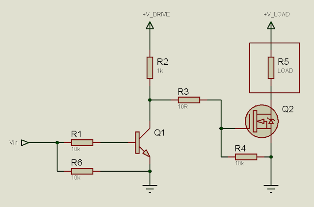
In many circuits, it is necessary to use MOSFETs for switching. In many cases, the MOSFET drive signals are generated by microcontrollers. In other cases, they are generated by ICs – PWM controllers, timers or any IC in fact. However, MOSFETs cannot always just be connected to the drive signal and be expected to work properly. Due to the construction of the MOSFET, driving it is not the simplest of tasks, especially for beginners. There are many users who regularly ask for help on MOSFET drive related issues or problems on different blogs, websites and forums. So, here I will show some MOSFET drive techniques/methods for MOSFETs configured as low-side switches. Before I head on to MOSFET drive, let me just tell you what a low-side switch is, in case you don't know. When the MOSFET (that you're using as a switch) sinks current, it is a low-side switch. The load will be between the drain and +V supply. The source will be connected to ground. Gate will be driven with respect to gr...
I had previously shown how to drive N-channel MOSFETs in low-side configuration. You can find the tutorial here: http://electel.blogspot.com/2016/12/low-side-mosfet-drive-circuits-and_23.html I’ve been requested to write a tutorial/article regarding high-side MOSFET drive. So, here I’ll talk about N-channel MOSFET high-side drive. Let’s first look at the common low side configuration. Fig. 1 - N-channel MOSFET configured as low-side switch Now let’s look at a MOSFET configured as a high-side switch. Fig. 2 - N-channel MOSFET configured as high-side switch You can quite easily see the difference between the high-side configuration and the low-side configuration. In the low-side configuration, the load is connected between the drain and +V, while the source is connected to ground. Thus, the gate drive is referenced to ground. So by applying a voltage of >7V (for Power MOSFETs) or >4V (for Logic Level MOSFETs), the MOSFET can be fully turned on. Now let’s talk about the high-si...
In many situations, we need to use MOSFETs configured as high-side switches. Many a times we need to use MOSFETs configured as high-side and low-side switches. Such as in bridge circuits. In half-bridge circuits, we have 1 high-side MOSFET and 1 low-side MOSFET. In full-bridge circuits we have 2 high-side MOSFETs and 2 low-side MOSFETs. In such situations, there is a need to use high-side drive circuitry alongside low-side drive circuitry. The most common way of driving MOSFETs in such cases is to use high-low side MOSFET drivers. Undoubtedly, the most popular such driver chip is the IR2110. And in this article/tutorial, I will talk about the IR2110. You can download the IR2110 datasheet from the IR website. Here's the download link: www.irf.com/product-info/datasheets/data/ir2110.pdf First let’s take a look at the block diagram and the pin assignments and pin definitions (also called lead assignments and lead definitions): Fig. 1 - IR2110 block diagram (click on image to enlarge)...


My browser warns me that the link you have posted contains harmful software and it won't let me see it, even when I agree to the risk the URL won't load. Could you post the info here or fix the link?
ReplyDeleteI would appreciate it very very much.