Posts

Showing posts from October, 2016

Interfacing a color TFT display with the PIC32MX250F128B

Image
I have been working on interfacing the PIC32MX250F128B with a small 2.2" TFT display from Adafruit. It's a nice little display that is fairly easy to communicate with, using SPI communication. The display I'm using is: http://www.adafruit.com/product/1480 Adafruit provides nice open-source libraries for their products. However, they are for Arduino and thus cannot be directly reused for the PIC32. I went through the library and ported it over for the PIC32, in C. I have attached my project file as a .zip file and you can download it to go through the library header and source files, as well as the demo code. I've tried heavily commenting the code so that it is self-explanatory. As far as hardware goes, with the demo code, the pin connections for the display are: BL (backlight): I left it unconnected, but you can connect it to 3.3V for backlight. SCK: connected to RB14 on the PIC MISO: left unconnected, since I'm not reading anything from the screen MOSI: connected ...
Image

Zero crossing detection with PIC16F877A

Image
Zero crossing detection is very important, especially in power control circuits employing thyristors. I have come across many people struggling with zero crossing detection with PIC microcontroller and thus they cannot fire triacs or SCRs as required. So, here I have explained a simple method of detecting zero crossing with PIC16F877A, employing only two or three resistors, a bridge rectifier and an optocoupler for the hardware portion of zero cross detection.  The PIC 16F877A detects the zero crossing using the RB0/INT external interrupt function. I have explained how the zero cross is detected and how the PIC acts upon detection, below.   Fig. 1 - Schematic, zero crossing signal and RD0 signals --------------------------------------------------------------------------------------------------------- Here is the code for PIC16F877A: (You can download the source file from https://rapidshare.com/files/604474700/ZeroCrossing.c ) -------------------------------------------------...

Temperature Sensor (MCP9700 + PIC16F877A)

Image
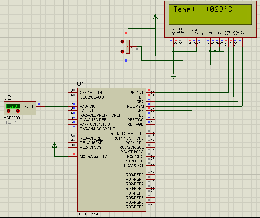
Here's a temperature sensor (thermometer) circuit that you can easily build. It uses the popular PIC 16F877A microcontroller. The temperature sensor is MCP9700. The MCP9700 outputs an analog voltage corresponding to the temperature. The PIC reads the analog voltage, processes it and displays temperature on the LCD. The temperature range of this circuit is -40'C to +125'C. The methods of processing the output of the MCP9700 can be found in the datasheet: ww1.microchip.com/downloads/en/devicedoc/21942a.pdf  The analog to digital conversion is done by the PIC ADC module. In the code, I've used the mikroC library function for ADC. You can view the library file here: http://www.mikroe.com/download/eng/documents/compilers/mikroc/pro/pic/help/adc_library.htm However, you should have a knowledge of how the ADC module works and how to use it. I had written a tutorial on modalities of operation of the PIC 16F877A ADC. You can find the tutorial here: http://electel.blogspot...

Temperature Sensor (DS18S20 + PIC16F877A)

Image
Here's a temperature sensor (thermometer) circuit that you can easily build. It uses the popular PIC 16F877A microcontroller. The temperature sensor is DS18S20. The DS18S20 communicates through the one-wire protocol. The PIC16F877A communicates with the DS18S20 with the one-wire protocol and gets the information for the temperature and displays it on the LCD. The temperature range of this circuit is -55'C to +125'C. The methods of communicating with the DS18S20 and sending/receiving commands, and reading the temperature value,  are all explained in the DS18S20 datasheet ( datasheets.maximintegrated.com/en/ds/DS18S20.pdf ). Here is the code for the PIC16F877A: (You can download the source file from: https://rapidshare.com/files/1817975964/DS18S20PIC16F877A.c ) -------------------------------------------------------------------------------------------------------------- //Programmer: Syed Tahmid Mahbub //Compiler: mikroC PRO for PIC v4.60 //Target PIC: PIC16F877A ----------...

Temperature Sensor (LM35 + PIC16F877A)

Image
Here's one temperature sensor (thermometer) circuit that you can easily build. It uses the popular PIC 16F877A microcontroller. The temperature sensor is LM35. The LM35 outputs an analog voltage proportional to the temperature. The output from the LM35 is 0.1V/'C. So, when temperature sensed is 61'C, the output voltage is 0.61V. This analog voltage is read by the PIC and processed to display the corresponding temperature value on the LCD. The temperature range for this circuit is 0'C to 150'C. The analog to digital conversion is done by the PIC ADC module. In the code, I've used the mikroC library function for ADC. You can view the library file here: http://www.mikroe.com/download/eng/documents/compilers/mikroc/pro/pic/help/adc_library.htm However, you should have a knowledge of how the ADC module works and how to use it. I had written a tutorial on modalities of operation of the PIC 16F877A ADC. You can find the tutorial here: http://electel.blogspot.com/2016/0...

NE555 Example Project: Light detector

Image
NE555 Operation The NE555 comprises 23 transistors, two diodes 16 and resistors which form four elements: two operational amplifiers Compare type; an inverter logic gate; SET and RESET latch. The NE555 can operate in three modes: monostable, astable or bistable. I will detail precisely two in this article, the third being extremely simple. Astable operation For me, this is the simplest operation. This configuration allows to use the 555 as oscillator which will generate a square wave signal at its output. The astable word means that the timer has no stable state.

MAGIC of knowledge

I turned the switch on and BOOM! That noise, the tiny puff of smoke and the accompanying smell had become far too familiar. I looked on in confusion at all the failed electronics components in front of me. I needed answers. Why did the H-bridge circuit not work as “claimed”? Books showed numerous such circuits. The Internet was not short of designs either. They were all similar though. I had done my research. I thought I understood the principles and modalities of operation. Then, where did the fault lie? Frustration was creeping in. But I just had to find the fault and fix it. I wanted to make the SMPS based inverter because I could learn so much in a field completely new to me and then use the inverter at home during power cuts. In that one night of experimentation, I had failed repeatedly, damaging 24 IR2110’s and a lot more components. I had applied all I had learned thus far. Success, however, eluded me. After repeated failures, I posted my problem on online electronics forums. Nu...

PIC32 DMA+SPI+DAC : Analog output synthesis with zero CPU overhead

Image
I have previously shown how to use the PIC32 SPI module to use the 12-bit DAC MCP4822: http://electel.blogspot.com/2016/10/pic32-spi-using-mcp4822-12-bit-serial.html . While that does allow you to generate analog outputs as desired, it requires you to use CPU cycles to process the timer interrupt and accordingly drive the SPI module. Since the PIC32 contains DMA channels, the process can be completely offloaded from the CPU. For an idea of the PIC32 DMA module, refer to my previously written article: http://electel.blogspot.com/2016/05/simple-pic32-dma-example.html Fig. 1 - The generated sine wave at fpwm = 400kHz and 32 elements in the sine table So, the simple way of offloading the SPI update to the DMA module would be to let the DMA channel transfer data to the SPI buffer. The SPI module is configured for 16-bit data transfer (since the MCP4822 write command requires 2 bytes). This means that the cell size for the DMA channel has been set to 2 (2 bytes to transfer once triggered). T...

PIC32 SPI: Using the MCP4822 12-bit serial dual DAC

Image
I recently got a few pieces of the MCP4822 DAC. You can check out the datasheet here: http://ww1.microchip.com/downloads/en/DeviceDoc/22249A.pdf I found them to be neat little devices. In a small 8-pin PDIP package, the MCP4822 comes with 2 12-bit DACs, which you can easily configure over SPI. This was a great opportunity to get a simple PIC32 SPI application going. I worked on this today to see how fast I can get the DAC output going. Here's the pinout of the MCP4822: Fig. 1 - MCP4822 pinout (taken from datasheet) The MCP4822 can be supplied a voltage in the range of 2.7V to 5.5V. Since I use 3.3V for my PIC32, I used the same 3.3V supply for the VDD for the MCP4822. Pin 5 is the active low signal LDAC that is used to synchronize the two DAC channels. When this pin is brought low, the data in the DAC's input register is copied to the output and both outputs are updated at the same time. I just had this tied to ground. VoutA and VoutB are the two output pins. The other pins are...

Smart Sine - Software to generate sine table

Image
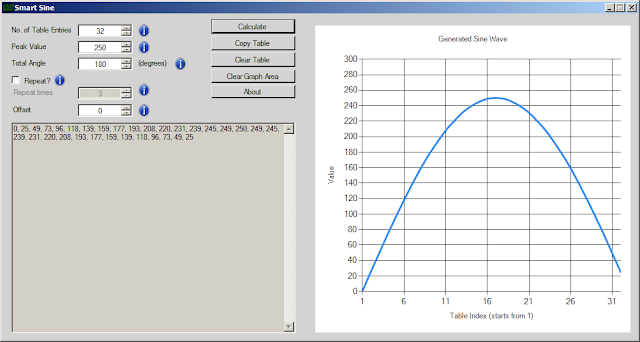
Here is the software Smart Sine, that I created and now use to generate sine tables. It is the improved and more developed version of the software I had previously created with a few more useful features. It is relatively simple to use and gives results quickly as opposed to manually calculating the table. If the software asks for .NET Framework Installation, you can download it from: http://www.microsoft.com/en-us/download/details.aspx?id=17851 or http://www.filehippo.com/download_dotnet_framework_4/ Download the software from : Recommended: https://drive.google.com/file/d/0B4SoPFPRNziHWVdLYVFKeHlsWjQ/view?usp=sharing Alternate link: http://www.4shared.com/zip/L2RbV7Hz/Smart_Sine.html Here are a few screenshots:

Generation of sine wave using SPWM in PIC16F684

Image
I have previously shown how to calculate the values for the sine table. Now I will show you how to use that sine table for generating a sine wave using a PIC16F684. Why PIC16F684? It is a nice little 14-pin PIC that contains all that is needed for SPWM (sinusoidal pulse width modulation) – the ECCP module. Since the ADC or comparator or other peripherals are not used and there are enough pins, I selected the PIC16F684. You can find the tutorial here: http://electel.blogspot.com/2016/01/generation-and-implementation-of-sine.html Let’s run the 16F684 from a 16MHz crystal oscillator and use a 16kHz switching frequency. So, the required value of PR2 is 249. The sine table (for half a cycle) is: 0, 25, 49, 73, 96, 118, 139, 159, 177, 193, 208, 220, 231, 239, 245, 249, 250, 249, 245, 239, 231, 220, 208, 193, 177, 159, 139, 118, 96, 73, 49, 25 ''''''''''''''''''''''''''''''...

600W 50Hz sine wave inverter test circuit

Image
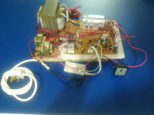
Here I tested a 600W 50Hz sine wave inverter circuit using push-pull topology instead of full-bridge topology. 2 PIC16F684's were used - one for SPWM and one for charging. 2 microcontrollers were used intentionally as the purpose was to test if I could use the microcontrollers together and use each of them for multitasking. 2 auxiliary transformers are used - one for powering the circuitry when running off mains and one for current sensing. Charging is done with 4 relays that are turned on/off according to input voltage and accordingly connect the input voltage to an appropriate transformer winding/tapping to keep output voltage relatively constant. Switching frequency is 16kHz. The sine table has 32 values. Here is the complete sine table: 0, 16, 32, 47, 62, 77, 91, 103, 115, 126, 136, 144, 151, 156, 160, 162, 163, 162, 160, 156, 151, 144, 136, 126, 115, 103, 91, 77, 62, 47, 32, 16, //65% 0, 17, 33, 49, 65, 80, 94, 107, 120, 131, 141, 149, 156, 162, 166, 168, 169, 168, 166, 162, 1...

SMPS TopoMagic

Image
When I started learning about and designing SMPS circuits in 2008, I read from various books and online resources – application notes, reference manuals, design notes, design tips, circuit designs and various tutorials. I understood most of the concepts. But the mathematics was complex and there were so many formulae and calculations. They were not all present in any single book or document. Making all the necessary calculations using the different formulae available in all the different documents was difficult, tiring and cumbersome. While I was learning SMPS and started getting a hold of the basics, I was learning Visual Basic at school. During the mid-year school break, I learnt from various tutorials online and practiced during the school vacation to develop my Visual Basic skills. After I learnt most of the basics, I decided to put my skills to the test. It would be good practice and I could make a useful program in the process. I started coding using the information present in va...