Posts

Showing posts from December, 2016

8051 SEVEN SEGMENT DISPLAY (SSD) INTERFACE

Seven Segment Display which is most commonly known as SSD is an output device which can be used to display information. As discussed in my previous post , it is necessary for a system to have proper input/output devices for assisting the user and SSD serves the very same purpose by displaying some useful information to the user. You can easily connect/interface it with 8051 MCU for output once you understand it properly. After reading this article, you will get to know everything about it. READ MORE

Using an input device on Embedded Linux: An example with a USB mouse on the Intel Edison

Image
The Intel Edison test board, along with the USB mouse I have recently been using the Intel Edison for the Cornell robotics project team (which co-hosts the Intel-Cornell Cup USA competition). Building on my previous knowledge of embedded systems, I started learning to use and program on Linux. The distro used is Yocto (all information is available on the Intel Edison website). One of the prototypes we worked on relied on using a wireless Playstation 4 controller for locomotion user interface. The concept of using an input device on Linux is not complicated, but can be a daunting task for someone new to Linux programming. Hence, I have decided to write this article giving an example of using an input device on an Embedded Linux platform. This demo application I am showing uses a USB mouse as the input device connected to the Intel Edison. Prerequisite: I have assumed that you have a flashed Intel Edison board, know how to access the terminal (through the USB COM port, or through SSH) a...

Ferrite Transformer Turns Calculation for High-Frequency/SMPS Inverter

Image
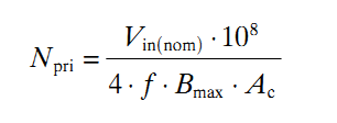
On different forums, I often find people asking for help in calculating the required turns for a ferrite transformer they are going to use in high-frequency/SMPS inverters. In a high-frequency/SMPS inverter, the ferrite transformer is used in the step-up/boost stage where the low voltage DC from the battery is stepped up to high voltage DC. In this situation, there are really only two choices when selecting topology – push-pull and full-bridge. For transformer design, the difference between a push-pull and a full-bridge transformer for same voltage and power will be that the push-pull transformer will require a center tap, meaning it will require twice the number of primary turns as the full-bridge transformer. Calculation of required turns is actually quite simple and I’ll explain this here. For explanation, I’ll use an example and go through the calculation process. Let’s say the ferrite transformer will be used in a 250W inverter. The selected topology is push-pull. The power source...

Digital thermometer with LM35 and PIC18F452

Image
This can be a complete project on its own - a simple DIY digital thermometer with LCD display and only a handful of parts - the PIC18F452, LM35 and a small number of resistors and capacitors running off a regulated 5v supply. Temperature range - 0 to 150'C Display type - LCD (can be 16x1, 16x2 or anything larger) Controller: PIC18F452 Programming Language: BASIC Compiler: mikroBASIC PRO for PIC v3.20 ''''''''''''''''''''''''''''''''''''''''''''''''''''''''''''''''''''''''''''''''''''''''''''''''''''''''''''''''''''''...

Digital thermometer with LM35 and PIC16F88

Image
This can be a complete project on its own - a simple DIY digital thermometer with 7-segment displays and only a handful of parts - the PIC16F88, LM35 and a small number of resistors and capacitors running off a regulated 5v supply. Temperature range - 0 to 150'C Display type - 3 digit multiplexed 7 segment or 3 individual 7 segments Controller: PIC16F88 Programming Language: BASIC Compiler: mikroBASIC PRO for PIC v3.20 Complete code: '''''''''''''''''''''''''''''''''''''''''''''''''''''''''''''''''''''''''''''''''''''''''''''''''''''''''''''''...

Low-Side MOSFET Drive Circuits and Techniques - 7 Practical Circuits

Image
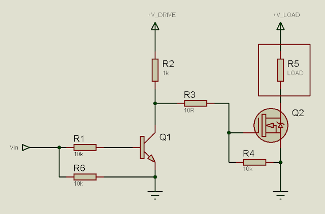
In many circuits, it is necessary to use MOSFETs for switching. In many cases, the MOSFET drive signals are generated by microcontrollers. In other cases, they are generated by ICs – PWM controllers, timers or any IC in fact. However, MOSFETs cannot always just be connected to the drive signal and be expected to work properly. Due to the construction of the MOSFET, driving it is not the simplest of tasks, especially for beginners. There are many users who regularly ask for help on MOSFET drive related issues or problems on different blogs, websites and forums. So, here I will show some MOSFET drive techniques/methods for MOSFETs configured as low-side switches. Before I head on to MOSFET drive, let me just tell you what a low-side switch is, in case you don't know. When the MOSFET (that you're using as a switch) sinks current, it is a low-side switch. The load will be between the drain and +V supply. The source will be connected to ground. Gate will be driven with respect to gr...

Learning SMPS the hard way

SMPS is the toughest section in Power Electronics. Tremendous knowledge is required for choosing active and passive parts for use in SMPS circuits. Special parts are often required specifically for use in SMPS. Many components that can be used for low frequency applications in Power Electronics may fail if used in SMPS circuits. When I started learning Power electronics in 2008, I placed emphasis on SMPS. Regarding SMPS, nothing was available here. I had to collect and gain everything piecemeal- knowledge, literature, active and passive parts, testing equipment etc. The main drawback was the lack of knowledge in this field. In my country, SMPS is not taught in detail in any engineering university. So, teachers are not readily available. Additionally, relevant books were also not available. So, my father chalked out a deliberate and detailed plan for me to learn SMPS: Detailed Plan for learning SMPS at home Step 1   – Collecting knowledge by collecting required books from ab...

8051 SWITCH INTERFACE

It is necessary for every system to have proper user interface - which makes it user friendly and easy to operate. For instance, imagine using your computer without the monitor (display), keyboard or mouse? It's not even possible to operate it without these essential components as they help you either in entering data (input) to the PC or seeing the results on screen (output). Similarly, an embedded system (the one involving microcontrollers such as 8051 in our case) also require input/ouput devices to be user friendly. A switch can act as an input device to the microcontroller unit (MCU) and this post is all about interfacing/connecting it to the 8051 MCU. READ MORE

Single microcontroller based 12v to 230v inverter with intelligent battery charging

Image
 Single microcontroller based 12v to 230v inverter with intelligent battery charging (Made by me) Here I describe the circuit as: *single microcontroller/controller (ATMEGA16/32) *no op-amps, only chips are the micro, opto-couplers and regulator (7805) *low-battery/overload/short-circuit protection *thyristor controlled battery charger, using the MOSFET body diode as the AC-DC rectifier *charger maintains the battery voltage (top) between 13.2-13.5v (adjustable) to maximize the battery life *6-LED display *Only 93 parts in entire control circuit *Delay between switchover to prevent inrush current The method used here, described for those who may benefit from it: -Initialize all ports and peripherals[ADC, Timers, Compare Modules] -Initialize interrupts for Timer0 and compare module for -For PWM, use Timer1 and 16-bit Phase and Frequency Correct PWM mode so the PWM runs completely on the hardware level without need for interaction to keep it running -The AVR senses whether mains is p...

Basic Theory on AVR Timer0

Image
To start off with, the formulae relating duty cycle, frequency and time period is: f=1/T, D=t/T where D is duty cycle, T is time period, t is on time, f is frequency Vo = D * Vin, where Vo = average voltage output from AVR pin, D = duty cycle, Vin = Supply Voltage, eg 5v The output voltage here is in the form of pulses not a complete analog value. Eg. When frequency is 100Hz, duty cycle is 50% and supply voltage to AVR is 5v, then output from AVR pin is 2.5v. However, this does not mean that the output will be 2.5v DC. The output will be a pulsating output with frequency = 100Hz, 50% on, 50% off, with high state or on state voltage = 5v, low state or off state voltage = 0v. Therefore output = 2.5v, but actually 5v with 50% on and 50% off. This CAN be converted to pure DC by placing an RC or LC filter, which will convert the pulsating DC to a clean fixed DC voltage. I will refer to ATMEGA8 for example, as this seems to be one of the most popular AVRs. T...

PIC32 JTAG Loader / ICSP programmer

This past semester, I worked on an independent study/project where I explored the programming of the PIC32. I've provided the details in the following PDF document. The key takeaway I believe is: "This document presents sufficient background information on the project, and implementation specific details. The most important contribution this makes is adding the experiences and a full implementation of the project. For even more detail and a thorough understanding, it is recommended that this report be read along with the reference documents mentioned in Section 4.1." I plan on improving this, as well as exploring the option of programming other PICs this summer. A cursory look made me think that the PIC32 programming standard was more complicated than the PIC16's. I'll find out! All the project code and settings can be found here . This includes the PIC32 project, as well as the MATLAB code for the programmer software https://drive.google.com/open?id=0B4SoPFPRNziH...

8051 LED TOGGLE PROGRAM CODE

You might have seen a " Hello World! " program code example while learning some programming language. While it is useful for getting familiar with the basics of that language, it also gives you a head start in that environment. If you ever want to learn some new programming language, you might want to Google out a "Hello world!' program code to get started. The code I am about to discuss serves the same purpose for the 8051 microcontroller because it is the most simplest task to perform. Play close attention if you want everything to work properly. READ MORE