Posts

Showing posts from August, 2016

Addressing Modes of 8051

What is an addressing modes ? In short ,a way to addressing a operand is nothing but addressing mode. Operand means data on which we are going to operate i.e source data. We can address the operand using direct address or by using register or we can address the data using some numerical value etc. e.g. MOV A,#6BH In this example 6BH  is operand i.e. source data. After execution of this instruction 6BH is added to the accumulator.We can execute this instruction by using 5 different ways i.e we can use 5 different addressing modes to execute this instruction. Following are the different type of addressing modes.  Immediate addressing mode   Direct addressing mode  Register addressing mode  Register indirect addressing mode   Indexed addressing mode. Immediate addressing mode : As word indicate 'immediate' this addressing mode transfer 8 bit immediate data to destination . e.g MOV A, #6BH This instruction moves immediate data hex 6B to accumulator. In this addressing mode we use &

Memory organization 8051

Image
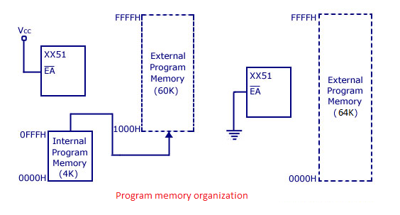
Memory organization is depends on type of architecture used. There are two type of architectures are used in controller or processor generally : 1) Von Neumann architecture 2) Harvard architecture Von Neumann architecture The term Von Neumann architecture, also known as the Von Neumann model or the Princeton architecture. This  architecture consist of address memory and data memory on a single unit . 8085 is based on Von Neumann architecture. Harvard architecture Harvard architecture consist of program memory and data memory as separate unit. Thus for accessing Harvard architecture we need separate address bus, data bus and control bus.  8051  is based on Von Neumann architecture.  Hence 8051 consist of two separate memory units, program memory as well as data memory. Program memory organization : The program memory organization for 8051 family is as shown in fig. above. 8051 microcontroller has an on chip internal  program ROM  of 4K size and if needed we can add an external memory of

Assembly Program Microcontroller 8051

Image
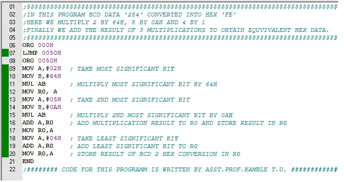
1. BCD 2 HEX Conversion.. Output :    Here "fe", HEX equivalent  of BCD data "254" is obtained in register r0 after the execution of this program.

Functional Pin Diagram of 8051

Image
Pin diagram : Micrcontroller 8051 is available in different packages in market DIP (Dual Inline Package),QFP (Quad Flat Package), TQFP (Thin Quad Flat Package), PQFP (Plastic Quad Flat Package) etc. Among them DIP package is mostly used. For explaining the pin diagram, we used here  40 pin DIP package. Pin configuration in detail is as given below : Pin-40 : We use this pin for power source Vcc . Usually its +5V DC.  Pins-32-39: We call this pin collectively Port 0 (P0.0 to P0.7) – It can be used as an I/O port as well as lower order address and data bus signals are multiplexed with this port  for external memory interfacing. It  is a only one bi directional I/O port in microcontroller 8051, it requires  external pull up resistors  to function this port as I/O port. Pin-31: We call this pin as 'ALE' i.e. Address Latch Enable which is used to demultiplex the address and data signal of port 0 while external memory interfacing. Two ALE pulses are required for each machine cycle

Introduction to 8051 Microcontroller

Image
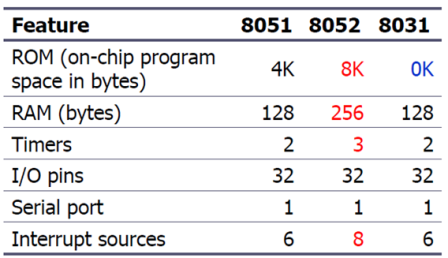
A microcontroller is nothing but a small computer on a single integrated circuit , it consist of central processing unit, memory unit, and programmable input/output peripherals.  Memory  unit consist of ROM as well as RAM. Microcontrollers are generally  designed for embedded applications that is dedicated applications which different than  the  microprocessors which are  used in personal computers or general purpose applications. Intel made 8051, referred as MCS- 51, in 1981.The 8051 is an 8-bit processor, its mean that CPU can work on only 8 bits of data at a time.The 8051 became widely popular when Intel  allowed other manufactures  in the market to make any flavor of the 8051. MCS- 51 Family: The 8051 is a father of MCS-51 family because it is the original member of 8051 family.The 8052 is a subset of the 8051 The 8031 is a ROM-less 8051Add external ROM to it.You lose two ports, and leave only 2 ports for I/O operations. Features of 8051 : Following are the features of 8051. 64KB P

Introduction to stepper motor

Image
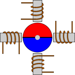
What is Stepper motor (step motor) ?? A stepper motor is a brush-less DC electric motor, it means that it converts electrical power into mechanical power.What make stepper motor different than other motor is the way it revolve.It rotate in steps unlike the other motors which rotates continuously, hence name given as stepper motor.Each step of motor is a fraction of full circle and its depends on hardware of motor and also driving method. Stepper motors are generally driven using pulse s instead of AC or DC power supply that's why it called as Digital motor also. It convert each pulse into degree of rotation, e.g. 4 degree stepper motor, It converts each pulse arrival into rotate rotor shaft of motor through 4 degree. Types of Stepper motor   Permanent magnet stepper motor The Permanent Magnet (PM)  motor is most basic type of stepper motor. Its rotor consist of a permanent magnet with 2 or more poles. The stator coils will attract or repulse the permanent magnet on the rotor  depe

8051 INTERFACING WITH LED, SWITCH, SSD AND KEYPAD

This is a wrap-up article for interfacing hardware with 8051 microcontroller. It's a combo deal for starters because this time, I have interfaced switches , LEDs , seven-segment-displa y and keypad all at the same time. I have already talked about them, individually, in my previous articles but for better understanding I think it's important to know how they work together. It will also give you some idea about dividing your code into segments and pieces which ultimately polishes your code writing skills. READ MORE

Timer/Counter Microcontroller 8051

Image
8051 has two 16-bit programmable UP timers/counters, T0 and T1 respectively.  we know 8051 processes on 8 bit data hence we have access to timer using  8-bit special function registers,  TL0 and TH0 for timer 0 and TL1 and TH1 for timer 1 respectively. We can use timer as an timer or counter. If we use timer as a timer then then clock source is on chip oscillator otherwise if we want to use timer as a counter then clock source is external clock. When we want to create delay using timer then we set some value in respective SFR's of timer. When timer is started  the value of SFR i.e value of count gets  incremented in every machine cycle. Thus, one can think of it as counting machine cycles. Hence we can say the clock rate for timer is 1/12 th of the oscillator frequency.  When we use timer as a counter, the respective SFR is incremented in response to a 1 to 0 transition at its corresponding external input pin (T0 or T1). It requires 2 machine cycles to detect a high to low transit

I/O Ports Microcontroller 8051

Image
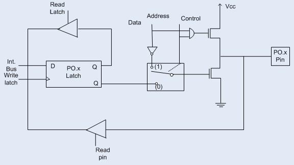
PORT 0 : The structure of a Port-0 pin is shown in fig 6.It has 8 pins (P0.0-P0.7). Add caption Port-0 can be used as a normal bidirectional I/O port or it can be used for address/data interfacing for accessing external memory. When control is '1', the port is used for address/data interfacing. When the control is '0', the port can be used as a  bidirectional I/O port. PORT 0 as an Input Port Let us assume that control is '0'. When the port is used as an input port, '1' is written to the latch. In this situation both the output MOSFETs are 'off'. Hence the output pin have floats hence whatever data written on pin is directly read by read pin.   PORT 0 as an Output  Port Suppose we want to write 1 on pin of Port 0, a '1' written to the latch which  turns 'off' the lower FET while due to '0' control signal upper FET also turns off as shown in fig. above. Here we wants logic '1' on pin but we getting floating

DEBUGGING IN KEIL

I have already written a brief post on how to use KEIL uVision in which I deliberately left the debugging part out because I wanted to talk about it at a proper time. I think it's now. If you haven't noticed it yet, KEIL uVision is also a debugger and will help you debug many of your codes and programs. The debugging environment of KEIL is very simple to understand and make use of. Today, I will introduce you to it. Ready? UPDATE: You can also click this link for an updated version of this post. READ MORE

HOW TO USE PROTEUS

The simulators I mentioned in my previous post were strictly for beginners. They just show you the output of the microcontroller so you can learn how everything works. They will accompany you as long as you are dealing with manipulating the data on the ports or registers. Sooner or later, you will be going further and attaching external hardware to the 8051 but that's exactly how we deal with it. So if you're talking about simulating a complete circuit then you actually need PROTEUS for this. UPDATE: You can also click this link for an updated version of this post with more insight and explanation. READ MORE